Control fan status, Operation, System diagram - typical enclosure options – Light Engineered Displays FS Series FAN STATUS & CONTROL User Manual
Page 2: Model, Width x height, Fans, System components
FS
SERIES
CONTROL
FAN STATUS &
Consult the factory regarding custom sizes, products, options or special requirements.
Normal operation is with the panel switches in the “AUTO” position. When the switch is placed in the “ON”
position, the appropriate fan-start relay will be energized. The relay contact will activate the fan. An auxillary
contact will send a signal back to the annunciator as positive indication that the function occurred. When the
switch is placed in the “OFF” position, the corresponding fan-disconnect relay will be energized. The relay
contact will interrupt the automatic fan-start signal from the fire control system.
The FSCS does not control the Smoke Evacuation fans directly. It is the FACP that provides the outputs that
control the fans and lights the Status indicators. Connections from the FSCS to the FACP are through conduit,
20’ or less in length. The switches and the LED indicators in the FSCS are wired to UL Listed terminal blocks
and from the terminal blocks directly to the Fire Control Product outputs.
"W"
"H"
4"
7/8"
Backbox
Graphic Door
For Semi-flush mounting, add 3” to overall “W” and “H” dimensions.
MODEL
FS-0
FS-1
FS-2
FS-3
FS-4
WIDTH x HEIGHT
9” x 18“
14” x 23 7/8“
23 7/8” x 24 1/2“
23 7/8” x 35”
36” x 48”
Operation
FANS
1 - 9
7 - 13
14 - 26
27 - 40
41 - 66
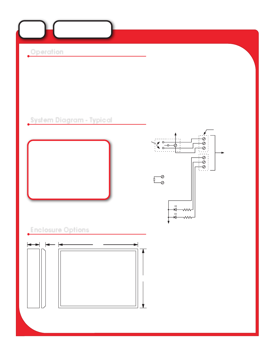
System Diagram - Typical
Enclosure Options
FAN "OFF"
FAN "ON"
SYSTEM COMPONENTS
KEYSWITCH - FOR USE TO
DISABLE / ENABLE THE FAN
CONTROL SWITCHES. TO
BE WIRED AS PER FCP
COMMON FOR ALL
FAN CONTROL SWITCHES
UL LISTED
TERMINAL STRIP IN
BACKBOX FOR FS
FOR CONNECTIONS
TO THE FCP.
TYPICAL OF ONE (1)
SWITCH GROUP TO
CONTROL ONE (1)
FAN STARTER.
ON
OFF
AUTO
COMMON FOR FAN
STATUS LED’S
MODEL
TS-2
TS-3
KS-2
KS-3
RS-2
RS-3
LED
DESCRIPTION
Two Position Toggle
Three Position Toggle
Two Position Keyswitch
Three Position Keyswitch
Two Position Rotary Switch
Three Position Rotary Switch
On/Off Indicators
A typical Fan Panel will require one control switch
and two indicators per fan.
Polarity and voltage may differ as per individual
fire alarm system requirements.
NOTE:
Units may be mounted Vertical or Horizontal