Table 1, Your vs-81sp 8 x 1 loudspeaker switcher – Kramer Electronics VS-81SP User Manual
Page 8
Your VS-81SP 8 x 1 Loudspeaker Switcher
5
5
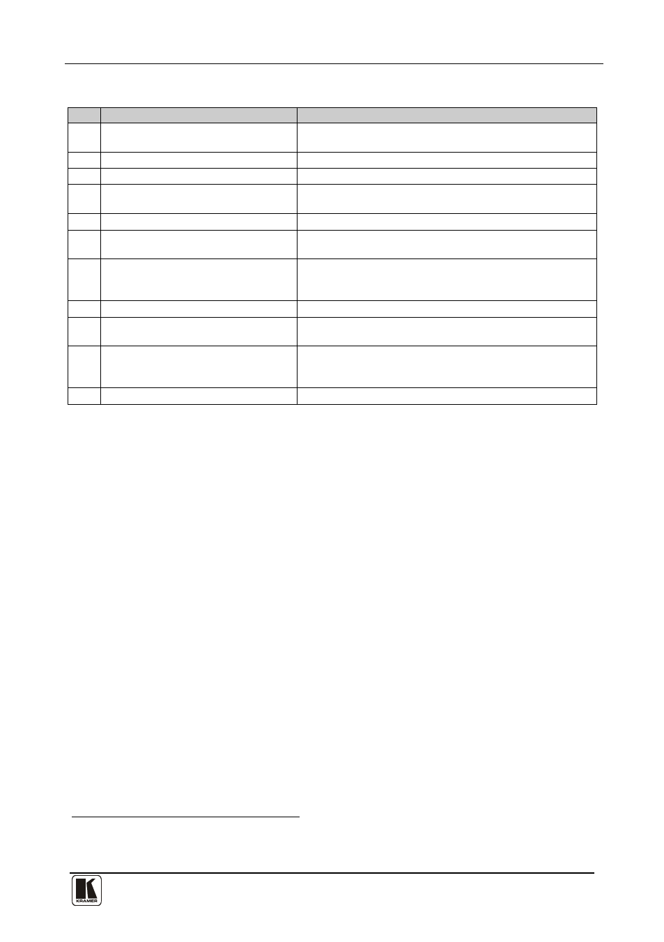
Table 1: VS-81SP 8 x 1 Loudspeaker Switcher Functions
#
Feature
Function
1
IR Receiver
The red LED illuminates when receiving signals from the
infrared remote control transmitter
2
POWER Switch
Illuminated switch for turning the unit ON and OFF
3
IN/OUT SELECTOR Buttons
Select which output (from 1 to 8) to switch from the input
4
OUT/IN Terminal Block Connectors
Connects to the input source(s) and the output speaker
pair(s) (from 1 to 8)
5
RS-232 IN 9-pin D-sub (F) Port
Connects to the PC or RS-232 remote controller
6
RS-232 OUT 9-pin D-sub (M) Port
Connects to the RS-232 IN 9-pin D-sub (F) port of the next
unit in the daisy-chain
7
SETUP DIP-switches
DIP-switches for setting up the unit (1 to 8 are for setting
addresses, 9 to 11 for software download, and 12 is for
RS-485 termination)
8
REMOTE Terminal Block Connectors
Connect to the remote contact-closure switches
9
RS-485 Terminal Block Port
Pins B (-) and A (+) are for RS-485, pin G may be connected
to the shield (if required)
10
REMOTE IR Opening
Connects to an external IR receiver unit for controlling the
machine via an IR remote controller (instead of using the front
panel IR receiver)
11
Power Connector with Fuse
AC connector enabling power supply to the unit
1 Optional. Can be used instead of the front panel (built-in) IR receiver to remotely control the machine (only if the internal
IR connection cable has been installed)