3 dip-switch settings, Dip-switch settings, Figure 5: controlling via rs-485 – Kramer Electronics VS-81SP User Manual
Page 13: Figure 5
KRAMER: SIMPLE CREATIVE TECHNOLOGY
Connecting the VS-81SP 8 x 1 Loudspeaker Switcher
10
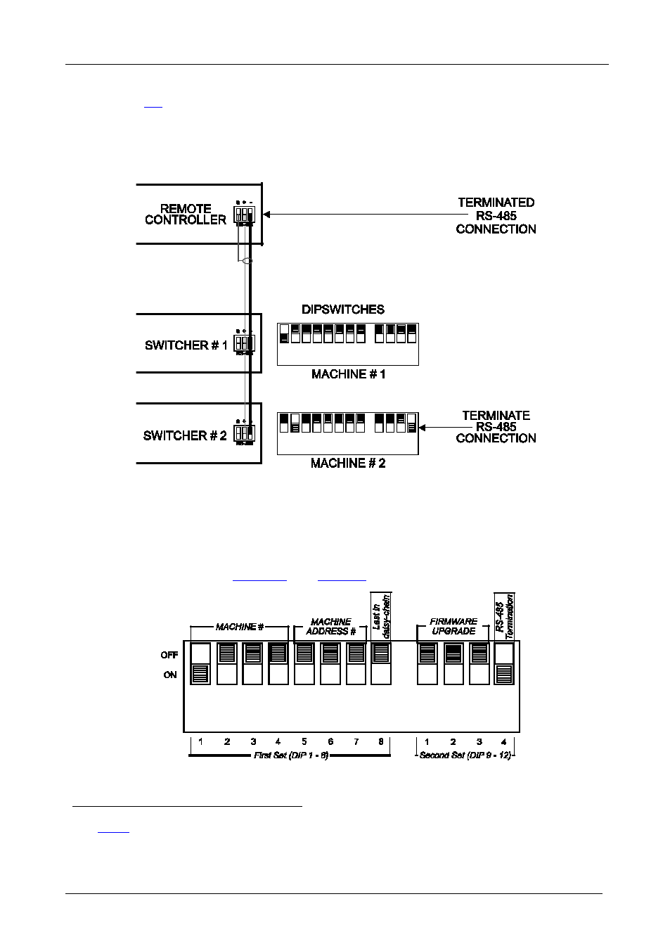
2. Set the SETUP DIP-switches on the VS-81SP units as follows (see section
):
• Set the first VS-81SP unit to MACHINE # 1
• Set the second VS-81SP unit to MACHINE # 2
and set DIP
12 to ON, terminating the RS-485 line
Figure 5: Controlling via RS-485
6.3
DIP-switch Settings
Configure the VS-81SP by setting the 12 SETUP DIP-switches (item 7 on
the rear panel), as
and
Figure 6: SETUP DIP-switches (Factory Default for Stand-Alone MACHINE # 1)
1 See
2 The RS-485 line must also be terminated at the remote controller. Refer to the remote controller’s user manual for details of
how to terminate the RS-485 line on the remote controller
See also other documents in the category Kramer Electronics Routers:
- VM-216H (25 pages)
- VM-28H (23 pages)
- VM-22H (12 pages)
- VM-24H (23 pages)
- VM-24HC (21 pages)
- VM-24HD (10 pages)
- VM-24HDCP (19 pages)
- VM-42 (8 pages)
- VP-222K (10 pages)
- VP-242 (8 pages)
- VP-32K (13 pages)
- VS-202YC (23 pages)
- 4x1S (15 pages)
- 4x1V (12 pages)
- 6241HDxl (10 pages)
- 6241N (10 pages)
- 6502 (12 pages)
- PT-201VGA (8 pages)
- TailorMade (21 pages)
- TailorMade (22 pages)
- VP-1201 (50 pages)
- VP-12x8 (34 pages)
- VP-1608 (46 pages)
- VS-88SDI (42 pages)
- VP-321xl (37 pages)
- VP-16x18AK (60 pages)
- VP-201xl (8 pages)
- VP-211K (15 pages)
- VP-27 (32 pages)
- VS-66HN (25 pages)
- VS-88HDxl (43 pages)
- VP-28 (42 pages)
- VP-2x2 (17 pages)
- VP-31 (25 pages)
- VP-311DVI (20 pages)
- VS-88HD (21 pages)
- VS-88HD (44 pages)
- VP-31KSi (16 pages)
- VP-81KSi (51 pages)
- VP-31KSi (48 pages)
- VP-41 (8 pages)
- VP-411DS (22 pages)
- VS-81HDxl (25 pages)
- VP-4x1CS (39 pages)
- VP-4x4K (61 pages)