Connecting an xga / audio switcher, 1 setting the machine, Table 8: machine # dipswitch settings – Kramer Electronics VP-161xl User Manual
Page 18
Connecting an XGA / Audio Switcher
15
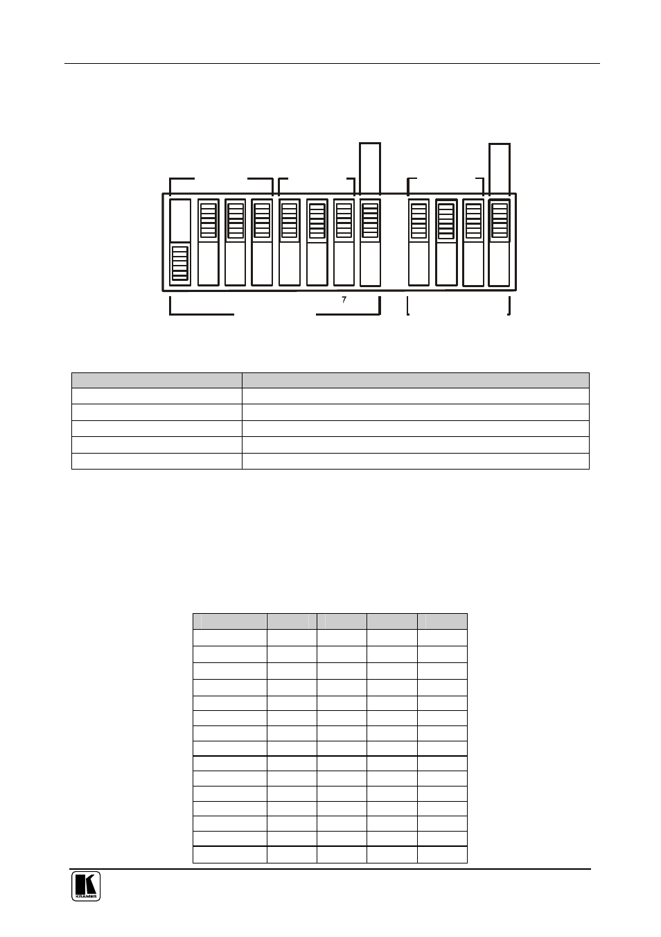
6.4 Dipswitch Settings
Configure the
VP-81xl, VP-161xl, and/or VP-321xl unit by setting the 12
SETUP dipswitches (item 13 on the rear panel), as Figure 9 and Table 7 define:
1
2
ON
3
4
5
MACHINE #
First Set (DIP 1 - 8)
Second Set (DIP 9 - 12)
MACHINE
ADDRESS #
1
2
3
4
La
st
in
da
is
y-
ch
ai
n
6
8
R
S
-4
85
Te
rm
in
at
io
n
FIRMWARE
UPGRADE
Figure 9: SETUP Dipswitches (Factory Default for Stand-Alone MACHINE # 1)
Table 7: Dipswitch Definitions
DIP
Function:
1-4
Set the MACHINE # (see section
6.4.1)
5-7
MACHINE ADDRESS # in daisy chain connection (see section 6.4.2)
8
Last in daisy chain
9-11 (marked 1-3 on second set) Firmware Upgrade (see section 8)
12 (marked 4 on second set)
RS-485 Termination (see section 6.3)
6.4.1
Setting the MACHINE #
To control a unit via RS-232 or RS-485, each unit has to be identified via its
unique MACHINE #. Set the MACHINE # on a
VP-81xl, VP-161xl, and/or
VP-321xl unit according to Table 8. A valid MACHINE # is from 1 to 15. For
a single, stand-alone machine, set as MACHINE # 1.
Table 8: MACHINE # Dipswitch Settings
MACHINE #
DIP 1
DIP 2
DIP 3
DIP 4
1
ON
OFF
OFF
OFF
2
OFF
ON
OFF
OFF
3
ON
ON
OFF
OFF
4
OFF
OFF
ON
OFF
5
ON
OFF
ON
OFF
6
OFF
ON
ON
OFF
7
ON
ON
ON
OFF
8
OFF
OFF
OFF
ON
9
ON
OFF
OFF
ON
10
OFF
ON
OFF
ON
11
ON
ON
OFF
ON
12
OFF
OFF
ON
ON
13
ON
OFF
ON
ON
14
OFF
ON
ON
ON
15
ON
ON
ON
ON