Kramer Electronics VP-161xl User Manual
Page 17
KRAMER: SIMPLE CREATIVE TECHNOLOGY
Connecting an XGA / Audio Switcher
14
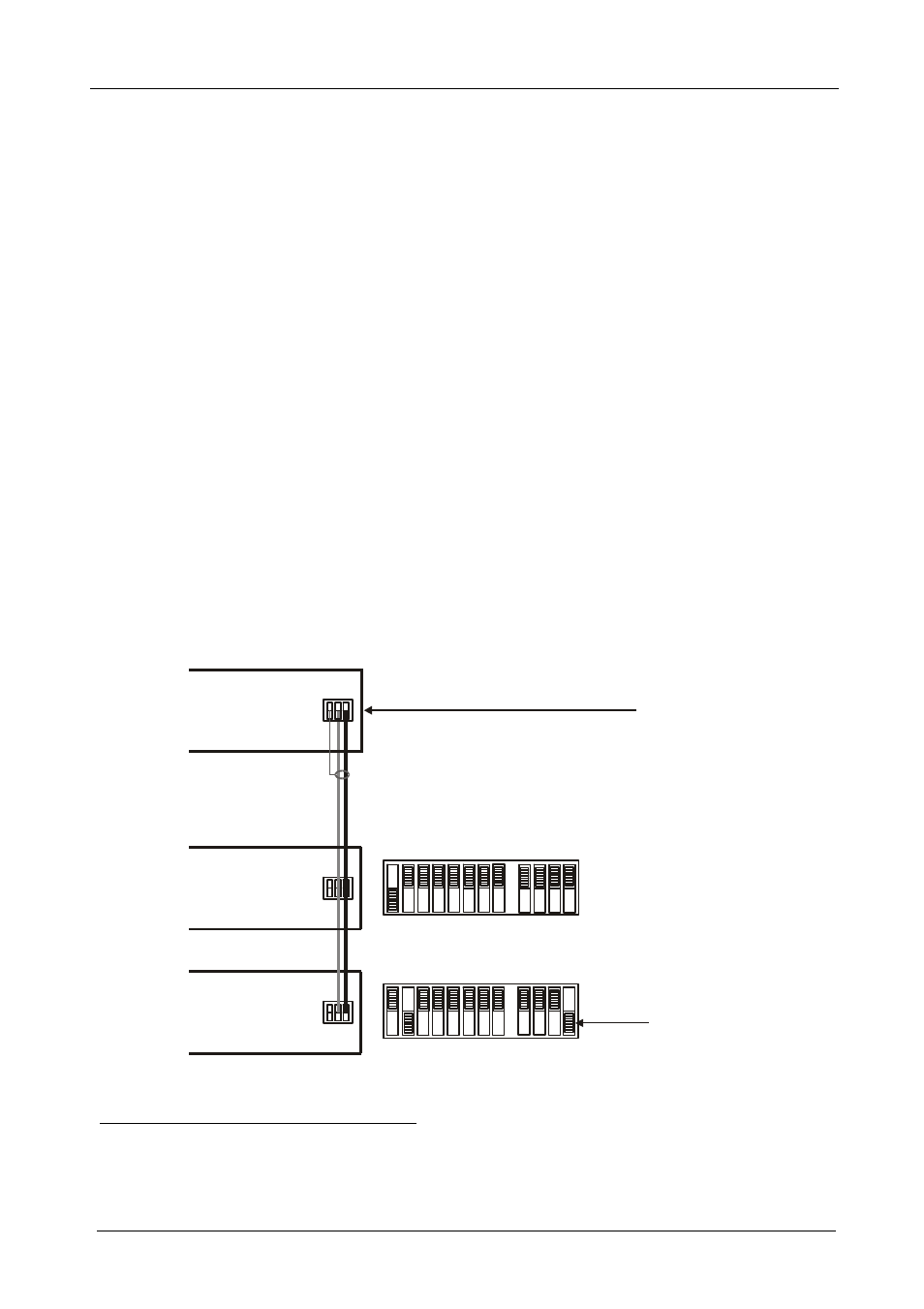
6.3 Controlling via RS-485
You can control a
VP-81xl, VP-161xl, or VP-321xl unit(s) via any RS-485
remote controller or a PC (equipped with an RS-485 interface).
To connect an RS-485 remote controller to two
VP-81xl/VP-161xl/VP-321xl
units (see Figure 8):
1. Connect the RS-485 port on the RS-485 remote controller to the RS-485 ports
on the
VP-81xl/VP-161xl/VP-321xl units, as follows:
Connect the “A” (+) PIN on the RS-485 remote controller to the “+” (A)
PINs on the RS-485 ports of the
VP-81xl/VP-161xl/VP-321xl units
Connect the “B” (-) PIN on the RS-485 remote controller to the “B” (-)
PINs on the RS-485 ports of the
VP-81xl/VP-161xl/VP-321xl units
If shielded twisted pair cable is used, the shield may be connected to
the “G” (Ground) PIN on one of the units (for example, on the
RS-485 remote controller)
2. Set the SETUP dipswitches on the
VP-81xl/VP-161xl/VP-321xl units as
follows:
Set the first
VP-81xl/VP-161xl/VP-321xl unit to MACHINE # 1
1
Set the second
VP-81xl/VP-161xl/VP-321xl unit to MACHINE # 2
1
and set DIP 12 to ON, terminating the RS-485 line
2
G
+ -
G
+ -
DIPSWITCHES
TERMINATE
RS-485
CONNECTION
TERMINATE
RS-485
CONNECTION
SWITCHER # 1
SWITCHER # 2
REMOTE
CONTROLLER
MACHINE # 1
MACHINE # 2
RS-485
RS-485
RS-485
G
+ -
Figure 8: Controlling via RS-485
1 See Table 8
2 The RS-485 line must also be terminated at the remote controller. Refer to the remote controller’s user manual for details of
how to terminate the RS-485 line on the remote controller