Table 10, Figure 12 and table 11 define the underside, Of the tp-124 xga/audio /data line receiver – Kramer Electronics TP-124 User Manual
Page 19
KRAMER: SIMPLE CREATIVE TECHNOLOGY
Your TP-123/TP-124
16
Table 10: TP-124 XGA/Audio/Data Line Receiver (Topside) Features
#
Feature
Function
1
12V DC
+12V DC connector for powering the unit
2
A
UDI
O
OU
T S/PDIF RCA connector
Connects to the digital audio acceptor
3
ANALOG 3.5mm mini jack
Connects to the analog audio acceptor
4
RS-232 Terminal Block connector
Connects to the controlled unit
5
LINE IN RJ-45 connector
Connects to
the LINE OUT RJ-45 connector on the
TP-123 or
the
TP-104
6
XGA OUT 15-pin HD (F) connector
Connect to the XGA acceptor
7
LINK LED
Illuminates when receiving the correct input signal
8
LEVEL trimmer
Adjusts
the output signal level
9
EQ.
Adjusts
10
the cable compensation equalization level
ON LED
Illuminates when receiving power
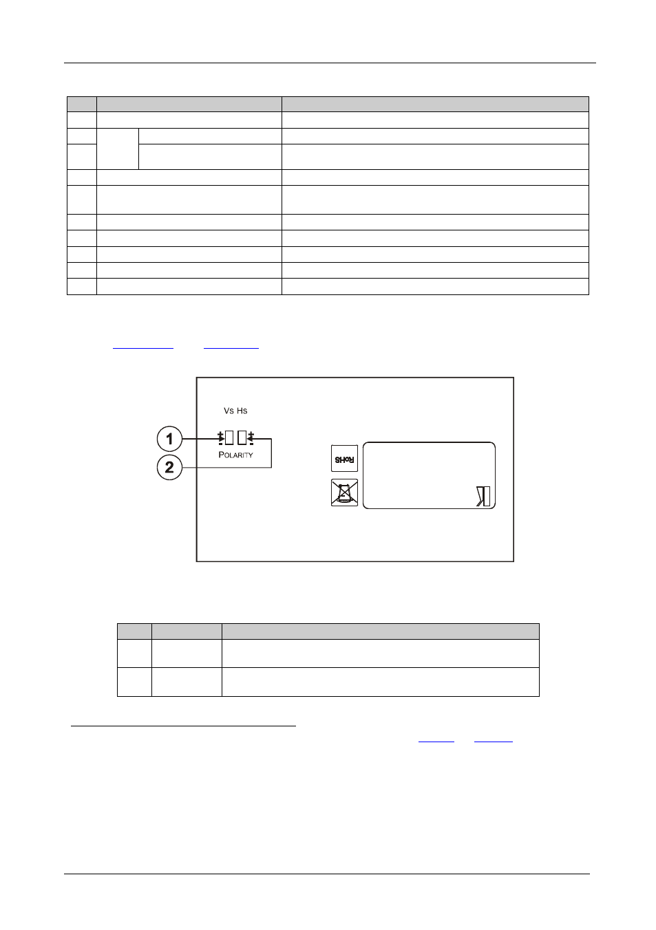
7.2.1 Your TP-124 XGA/Audio/Data Line Receiver (Underside)
/Data Line Receiver:
Figure 12: TP-124 XGA/Audio/Data Line Receiver (Underside
Table 11: TP-124 XGA/Audio/Data Line Receiver (Underside) Features
#
Feature
Function
1
VS Switch
Slide the switch up
to set the V SYNC to positive polarity;
slide the switch down to set the V SYNC to negative polarity
2
HS Switch
Slide the switch up
1 Using a UTP cable with CAT 5 connectors at both ends (the PINOUT is defined in
to set the H SYNC to positive polarity;
slide the switch down to set the H SYNC to negative polarity
2 The TP-104 does not accept the audio signals
3 Degradation and VGA/XGA signal loss can result from using long cables (due to stray capacitance), sometimes leading to a
total loss of sharpness in high-resolution signals
4 Use a screwdriver to carefully rotate the trimmer, adjusting the appropriate level
5 The underside is identical on the TP-122 and TP-124
6 By default, both switches are set down (for a negative V SYNC and H SYNC polarity)