1 the tp-123 internal polarity switches, The tp-123 internal polarity switches, Figure 10: tp-123 internal polarity switches – Kramer Electronics TP-124 User Manual
Page 17: Table 8
KRAMER: SIMPLE CREATIVE TECHNOLOGY
Your TP-123/TP-124
14
Table 8: TP-123 XGA/Audio/Data Line Transmitter Features
#
Feature
Function
1
12V DC
+12V DC connector for powering the unit
2
AUDIO IN 3.5mm mini jack
Connects to the audio source
3
RS-232 terminal block connector
Connects to the PC or the Remote Controller (see section
4
LINE OUT RJ-45
connector
Connects to
5
the LINE IN RJ-45 connector on the
TP-124
XGA/Audio Line Receiver
XGA IN 15-pin HD (F)
connector
Connect to the XGA source
6
ON LED
Illuminates when receiving power
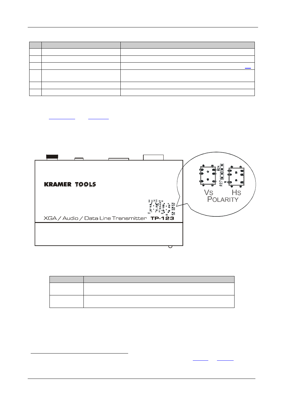
7.1.1 The TP-123 Internal Polarity Switches
define the internal sync polarity switches inside the
TP-123.
Note, that you need to open the TP-123 unit to gain access to the Vs and Hs
Polarity switches. After setting the switches, close the TP-123 unit.
Figure 10: TP-123 Internal Polarity Switches
Table 9: Features of the TP-123 Internal Polarity Switches
Feature
Function
VS Switch
Slide the switch down
to set the V SYNC to negative polarity (NEG.);
slide the switch up to set the V SYNC to its input polarity (NORM.)
HS Switch
Slide the switch down
to set the H SYNC to negative polarity (NEG.);
slide the switch up to set the H SYNC to its input polarity (NORM.)
1 Using a UTP CAT 5 cable with RJ-45 connectors at both ends (the PINOUT is defined in
2 By default, both switches are set down (for a negative V SYNC and H SYNC polarity)
NORM.
NEG.