Semi−rotary drive dfpb – Festo Неполноповоротный привод DFPB User Manual
Page 4
Semi−rotary drive DFPB
(en) Operating instructions
Original: de
749 613
0911b
Note
Fitting and commissioning is to be carried out only by qualified personnel in
accordance with the operating instructions.
1
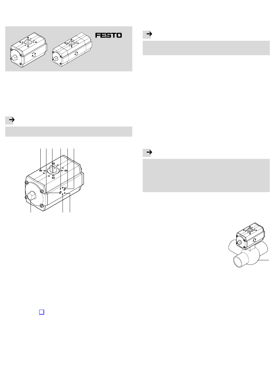
Operating elements and connections
1 2 3
5 6
4
4
5
Fig. 1
7
1
Different mounting threads on the
top and bottom of the DFPB for
installing a process valve or a limit
switch attachment
2
Port 2 (A) for the air supply for
actuating the switching shaft of
the DFPB in the direction of the
arrow (see housing top and
bottom)
3
Transmission shaft for mounting
the switching shaft of the process
valve or for mounting a square for
the limit switch attachment
4
Mounting thread for a solenoid
valve with NAMUR port pattern
5
Mounting thread for threaded pins
for aligning the NAMUR solenoid
valve
6
Port 4 (B) for the air supply for
actuating the switching shaft of
the DFPB against the direction of
the arrow (see housing top and
bottom)
7
Locking nut (for locking the
adjusting screws)
2
Function
Pressurizing the cylinder chambers causes the pistons in the DFPB to move back
and forth. Linear motion is converted into rotary motion by means of a rack and
pinion combination. A screwed−on process valve records the moment of reaction of
the DFPB. You can find the permissible nominal torque in the type designation of
the respective DFPB è Fig. 8.
3
Application
The DFPB semi−rotary drive is tailored completely to the requirements of the
processing industry. It is used for controlling media−flow process valves in systems.
The drive is properly used for process valves with a range of movement limited to
90°, suchĂas ball valves and butterfly valves (quarter turn actuators).
Use as a cushioning or shock absorbing element is not proper use. This may result
in excessive loads.
4
Transport and storage
· Ensure storage conditions as follows: short storage times in cool, dry, shaded
and corrosion−protected locations.
5
Conditions of use
Note
Incorrect handling can result in malfunctioning.
· Make sure that all the instructions in this chapter are observed. This way the
product will perform as intended.
· Use the product in its original state. Unauthorised modification is not permitted.
· Ensure that all applicable national and local safety laws are adhered to.
· Remove the packing except for the adhesive labels on the compressed air
connections (to prevent dirt).
· The packing is intended for recycling (except for: oiled paper = other waste).
· Compare the maximum values specified in these operating instructions with your
actual application (e.g. pressures, forces, torques, masses, response times,
temperatures). The product can only be used in accordance with the relevant
standards if the maximum load limits are observed.
· Take into consideration the ambient conditions at the location of use. Corrosive
environments reduce the service life of the product.
· Protect the device from fluctuations in pressure and excess operating
temperature. Use control valves for regulating pressure and excess pressure.
· Ensure that there is a supply of correctly prepared compressed air. The product
requires dried compressed air, lubricated or unlubricated.
· Use only non−lubricated compressed air under normal conditions.
The DFPB possesses an initial lubrication which suffices for the complete service
life.
Note
Continuous operation at the limits of the specified ambient temperature and
work frequency can reduce the service life of the semi−rotary drive.
· Use lubricated compressed air for continuous operation under extreme condiĆ
tions. The oil must be chemically inert and must not carbonise.
Using lubricated compressed air flushes out the initial lubrication.
· From that point onwards, the DFPB must be operated only with lubricated
compressed air.
If the DFPB is used in a potentially−explosive atmosphere:
· Please observe the notes and instructions in the accompanying ATEX special
documentation.
6
Fitting
The installation of the DFPB onto a process valve is
done in accordance with the desired direction of
rotation.
When a 3−way process valve
8 is used:
· Align the semi−rotary drive so that the connection
openings face the side without tubing. The
pneumatic connection must have a free working
space.
Fig. 2
8
6.1 Mechanical installation
· In order to fit the DFPB semi−rotary drive, set the switching shaft of the process
valve so that the desired working method for opening and closing the process
valve is implemented.
Observe the switching direction of the DFPB, shown by means of arrows on the
top and bottom of the device.
· Note that a process valve with butterfly valve can only be opened in one
direction.
· Note that the end position of the swivel motion can be adjusted:
ć on double−acting devices only in the direction of the arrow
ć on single−acting devices only against the direction of the arrow.