Figure 9: remote power connection – Muxlab Passive CCTV Hub Plus User Manual
Page 12
© MuxLab Inc.
Passive CCTV Hub Plus Installation Guide
Page 12
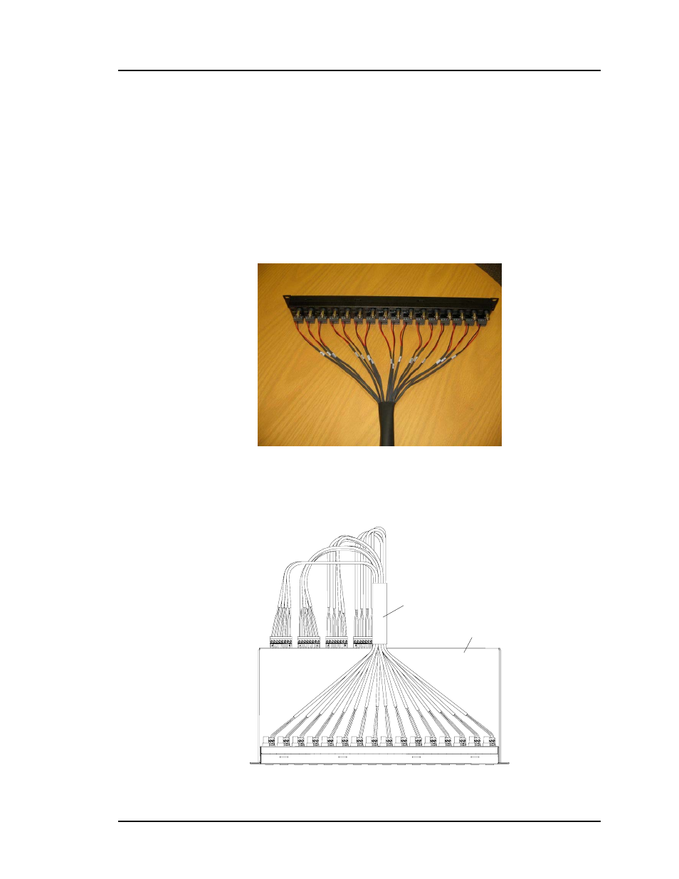
10. If remote power is being transmitted to the camera, verify that the distance
between the camera and the hub is within MuxLab specifications. Please
consult the distance charts at the back of the installation guide. When the
port switch is set to Pass-Thru Mode (500022), two (2) twisted pairs are
used for remote power. When the port switch is set to Power-Thru Mode
(500024/500029), three (3) twisted pairs are used for remote power thus
supporting greater distance. Connect the 16-channel 18/2 power cable
assembly to the hub by plugging each terminal block into the appropriately
number port on the hub.
11. Connect each set of two (2) wires from the power cable assembly to an
output power terminal on the CCTV power supply (fig 9). It is
recommended to use a Class II power supply with fuse protection on
each output port.
500134
Port 1
Port 16
Cable Assembly
Rackmount 16-channels CCTV PSU
Power terminals on PSU
Figure 9: Remote power connection
- CCTV Modular Balun (2 pages)
- Stereo Audio-Video Balun (2 pages)
- RGB Balun (2 pages)
- PTZ Balun (2 pages)
- VGA Balun (2 pages)
- Dual Audio-Video Balun (2 pages)
- Dual S-Video Balun (2 pages)
- LongReach™ (16 pages)
- S-Video Balun (2 pages)
- S-Video/Audio ProAV Balun (2 pages)
- S-VideoAudio GLI Balun (2 pages)
- Analog Audio Balun (2 pages)
- Digital Audio Balun (2 pages)
- Component Video Balun (2 pages)
- CCTV Pass-Thru Balun (2 pages)
- CCTV Power-Thru Balun (2 pages)
- CCTV Power-Thru Converter Balun (2 pages)
- MonoPro™ XLR (2 pages)
- Stereo Audio Balun (2 pages)
- Stereo Hi-Fi Balun (2 pages)
- Stereo Hi-Fi Wall Balun, UK (2 pages)
- Stereo Hi-Fi Wall Balun, US (2 pages)
- Stereo PC-Audio Balun (2 pages)
- Quad Video Balun (2 pages)
- Quad Audio Balun (2 pages)
- Quad Audio Wall Balun, UK (2 pages)
- Quad Audio Wall Balun, US (2 pages)
- Active VGA Balun Kit (15 pages)
- S-Video Hi-Fi Balun (2 pages)
- S-Video/Hi-Fi Wall Balun, US (2 pages)
- Stereo Hi-Fi Video Balun (2 pages)
- Stereo Hi-Fi/Video GLI Balun (2 pages)
- VGA Balun II (2 pages)
- VGA Wall Balun II, UK (3 pages)
- VGA Wall Balun II, US (2 pages)
- PS/2 Converter (2 pages)
- Stereo AV/IR Pass-Thru Balun (2 pages)
- Stereo AV/IR Pass-Thru Wall Plate Balun, UK (2 pages)
- Stereo AV/IR Pass-Thru Wall Balun, US (2 pages)
- Component Video/Digital Audio Balun (2 pages)
- Component Video/Analog Audio Balun (2 pages)
- Component Video/Analog Audio ProAV Balun (2 pages)
- Component Video/Analog Audio Wall Balun, UK (2 pages)
- Component Video/Analog Audio Wall Plate Balun, US (2 pages)
- Component Video/IR Pass-Thru Balun (2 pages)