Pin assignments mating connectors, P1 – rs485 bus interface, P2 – encoder interface – RMS Technologies R325P DRIVER User Manual
Page 7: P3 – motor/controls/power interface
5. PIN ASSIGNMENTS
Mating Connectors
P1
AMP 640441-3
P2
AMP 640441-5
P3
Phoenix 1803675
P1 – RS485 bus Interface
P1 Configuration
Pin No
Function
1
A Input (+ve)
2
Ground
3
B Input (-ve)
Table 5.1
P1 & P2 Location of Pin 1
Inage 5.1
P2 – Encoder Interface
P2 Configuration
Pin No
Function
1
Ground
2
Index
3
A
4
+5VDC
5
B
A motor with a single ended optical encoder
must be used in order for the encoder
feedback function to work. Connect the 5
wires from the encoder into P2 using a 5-Pin to
5-Pin connector which is provided with the
Designer’s Kit (purchased separately).
Table 5.2
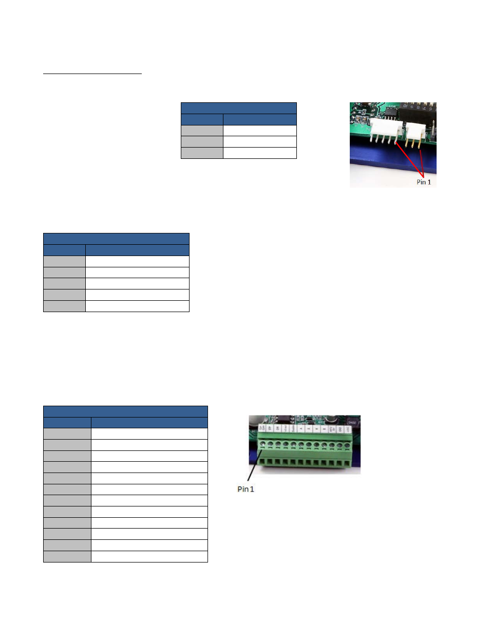
P3 – Motor/Controls/Power Interface
A 12-pin pluggable terminal strip connector P3 provides power and the step and direction control functions for
the module. All of these signals are optically isolated. Open-collector drives are required to provide pulses for
Step, levels for Direction, and Disable. The common +ve supply ranges from 5 VDC to 30 VDC with respect to the
signal input; however if the supply is greater than 5 VDC then a resistor must be inserted in series with each
signal line to limit the current to 10 mA.
P3 Configuration
Pin No
Function
1
Common +ve External
2
Step (in)
3
Direction (in)
4
+5 VDC Internal
5
Disable (in)
6
Motor A+ (out)
7
Motor A- (out)
8
Motor B+ (out)
9
Motor B- (out)
10
Full Step Output
11
Power Ground
12
Power Positive
P3 Connector – Pin 1 Location
Inage 5.2
Table 5.3
RMS Technologies
Page 7
Version 1.01
R325P Single Axis Driver Manual
5/29/2013