Assemble the single mechanical seal (1510-s) – Bell & Gossett P81673 REV I Series 1510 User Manual
Page 35
5
4
2
1
15
14
13
16
12
11
10
9
8
7
3
6
17
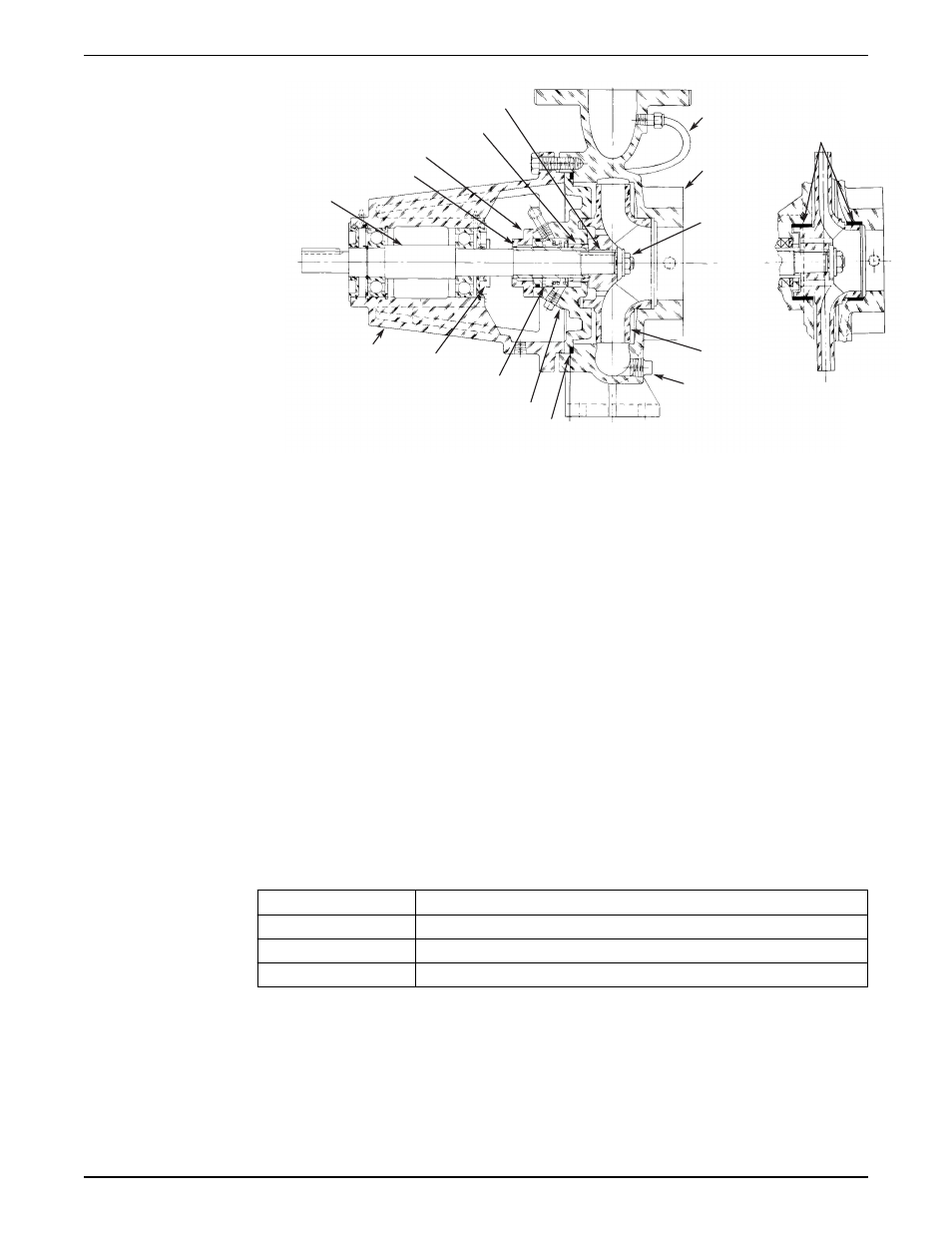
1.
Impeller Key
2.
Spacer Sleeve
3.
Gland
4.
Shaft Sleeve
5.
Shaft
6.
Bearing Frame
7.
Slinger
8.
Mechanical Seal
9.
Coverplate
10. O-Ring
11. Drain Plug
12. Impeller
13. Impeller Nut
14. Volute
15. Flush Tube
16. Wearing Ring
17. View of Optional Casing Wear Ring
Figure 9: 1510–8G
Assemble the single mechanical seal (1510-S)
1. Lubricate the shaft sleeve and seal cap with soapy water.
Do not use a petroleum lubricant.
2. Insert a stationary seal with an O-ring into the seal cap and slide it onto the shaft.
3. Replace the seal cap gasket.
4. Slide the rotating portion of the seal assembly onto the shaft sleeve and lock it in
place.
ID seal size
Distance between collar and impeller end of the shaft sleeve
1-1/4 in. (3.175 cm)
1-13/32 in. (3.571 cm)
1-5/8 in. (4.128 cm)
1-1/4 in. (3.175 cm)
2-3/8 in. (6.033 cm)
1-1/4 in. (3.175 cm)
5. Assemble the coverplate onto the bracket.
6. Tighten the capscrews according to the Capscrew torque table.
7. Attach the seal cap to the coverplate.
8. Tighten the hex nuts on the seal cap bolts according to the Capscrew torque table.
Maintenance
Series 1510 Installation, Operation, and Maintenance Manual
33
- 10 001 247 R3 TechnoForce Package System (36 pages)
- 10 001 265R5 TechnoForce Pump Controller (76 pages)
- 10-001-275 XLS Integrated Pump Controller (57 pages)
- 10-001-278 XLS Integrated Pump Controller (44 pages)
- 176R0649C Technologic 502 Series Pump Controller (74 pages)
- 193 TECHNOVAR VARIABLE SPEED PUMP CONTROLLER AND INTEGRATED AJUSTABLE FREQUENCY DRIVE (78 pages)
- 210667C Z-4 (2 pages)
- 210668B Z-4B (6 pages)
- 211013D PSE 800 M Low Water Cut-off (20 pages)
- MM 217L Series 150S and 157S Low Water Cut-Offs/Pump Controllers (12 pages)
- Iron & Bronze Booster Pumps Series 100 (4 pages)
- P2001487 Technologic Pump Controller (93 pages)
- P2000642B i-ALERT Condition Monitor (18 pages)
- P80922A Zone Trol Pump Controller ZT-1X (4 pages)
- P80925B Zone Trol Zone Pump Controller ZT-2 (6 pages)
- S11574C Heat Transfer Package with Air Separation (8 pages)
- S11865A TECHNOLOGIC 1100 SERIES PUMP CONTROLLER (4 pages)
- 70E Multiple Pump & Control Pressure Booster Systems (28 pages)
- S12260 R4 Genuine Bell & Gossett Replacement Seal Kit (1 page)
- S12596B Technologic 350 Pump Controller (24 pages)
- S13213A MiniBooster Pumping Package (10 pages)
- S13641B Technologic 5500 Series Pump Controller (38 pages)
- S13654B Technologic 5500 Series Pump Controller (31 pages)
- S14141B 70X Multiple Pump Pressure Booster Systems (12 pages)
- S14333 Technologic 5500 Series ZoneSav Controller (38 pages)
- S14334B Technologic 5500 Series Variable Primary Pump and Valve Controller (54 pages)
- S14362C Glycol Make-up Unit (10 pages)
- S14367B Technologic Constant Speed Pump Controller (44 pages)
- 6 71 075 003A Autocirc Instant Hot Water Pump Models e3-4/BDPQC (8 pages)
- 6 71 075 110A The ecocirc auto/vario Series Pumps (4 pages)
- 6 71 075 111A Autocirc Instant Hot Water Pump Model ecocirc 23 5 ACT (8 pages)
- 6 71 075 114A Series e3 SC Solar Circulators (6 pages)
- 6 71 075 115A LS Condensate Removal Pump (6 pages)
- 6 71 075 141B ecocirc wireless Potable Hot Water Recirculation Kit (28 pages)
- A 00 091 365A Series e3 4/e3 6 Instant Hot Water Recirculating Systems (6 pages)
- A 00 091 391A Automatic Plug-In Timer for e³-4/e³-6 Circulators (2 pages)
- A91590B DB-3/4″ Differential By-Pass Valve 3/4″ x 3/4″ NPT Male Connections Operational Limits (2 pages)
- A91591 Number 98 High Capacity Air Vent 1/2″ Female NPT Connection Operational Limits (3 pages)
- AC8584D Series HSCS Base Mounted Centrifugal Pumps (32 pages)
- IM207R00 Series 3530 (24 pages)
- IM228R04 e-SV (64 pages)
- MN 414 AC Submersible Pump Motors (16 pages)
- P0002560 Wireless Module and RS-485 Module (8 pages)
- P15758C Replacing the Bearing Frame Assembly or Pump Shaft (5 pages)
- P15776H Little Red Booster Pumps (4 pages)