Typical installation, Special installation, Install the pump, driver, and coupling – Bell & Gossett P81673 REV I Series 1510 User Manual
Page 17: Typical installation special installation
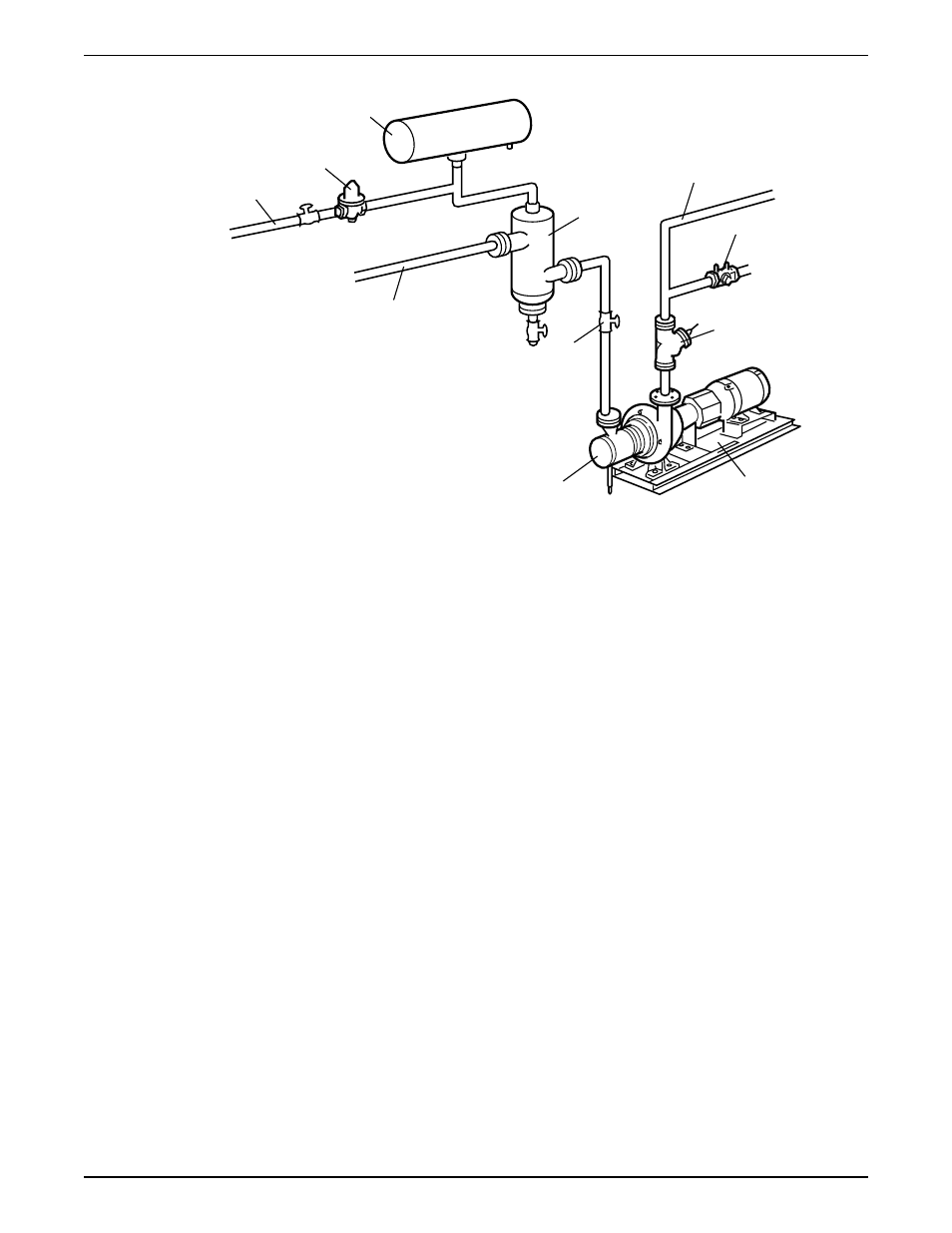
Typical installation
4
5
6
7
8
10
9
1
2
3
11
1.
Compression tank (locate the compression tank on the suction side of the pump)
2.
B&G Rolairtrol
®
air separator
3.
Supply to system
4.
B&G Circuit Setter
®
5.
B&G Triple Duty
®
valve
6.
B&G Series 1510 Pump
7.
B&G Suction Diffuser
8.
Isolation valve
9.
Pipe from boiler, chiller, or converter
10. Cold water supply
11. B&G Reducing Valve
Special installation
Installation with suction diffuser and triple-duty valve
Do not install and operate triple-duty valves and suction diffusers in closed systems unless
the system is designed with these safety and control devices:
• Pressure relief valves
• Compression tanks
• Pressure controlling equipment
• Temperature controlling equipment
• Flow controlling equipment
Check that the control and safety devices have these characteristics:
• Properly sized for their purpose
• Placed correctly in the system before putting the system into operation
Installation with isolation base
When using an isolation base, flexible piping should be used on both suction and
discharge sides to reduce the strain on the flanges.
Install the pump, driver, and coupling
Perform these steps only if the unit was not installed at the factory.
1. Mount and fasten the pump on the baseplate. Use applicable bolts.
2. Mount the driver on the baseplate. Use applicable bolts and hand tighten.
3. Install the coupling.
See the installation instructions from the coupling manufacturer.
Installation
Series 1510 Installation, Operation, and Maintenance Manual
15