Remove the coupling, Remove the bearing frame and impeller assembly – Bell & Gossett P81673 REV I Series 1510 User Manual
Page 31
Do not spread the outer and inner guards more than necessary to remove the guard.
It could alter their fit and appearance.
3. Remove the capscrew that holds the inner guard to the support bracket.
4. Spread the inner guard apart and pull it over the coupling.
1
2
3
4
5
6
12
10
9
8
7
11
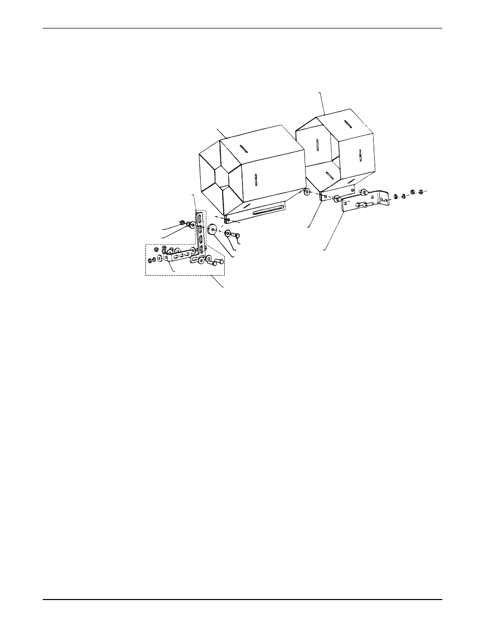
1.
Outer guard
2.
Inner guard
3.
Attach the support bracket inline with the bolt
4.
Support bracket
5.
Nut
6.
Lockwasher
7.
Capscrew
8.
Flat washer
9.
Spacer washer
10. Option used instead of the spacer where overall guard length exceeds 12 in. (30 cm) or
the guard width is over 10 in. (25 cm) across the flats
11. Locate the support arm between the outer guard ends. Align the arm with holes in the
outer guard and holes in the saddle bracket.
12. Motor saddle bracket attached to the motor saddle
Figure 8: Hex guard exploded view for typical installation
Remove the coupling
1. Loosen the setscrews in both coupling halves.
2. Slide each half as far back as possible on the shaft.
3. Remove the sleeve.
If you use a full-diameter impeller, you might have to remove the pump-side coupler half
and slide the motor back on its base. This allows you to gain sufficient clearance in order
to remove the pump assembly from the volute.
Remove the bearing frame and impeller assembly
1. Remove the support foot capscrews.
2. Loosen the volute capscrews but do not remove them.
3. Use the capscrews in the jackscrew holes for all models except for the 1510-8G.
4. Loosen the bearing frame and impeller assembly from the volute.
Maintenance
Series 1510 Installation, Operation, and Maintenance Manual
29