Disassembly, Disassembly precautions, Drain the pump – Bell & Gossett P81673 REV I Series 1510 User Manual
Page 30: Remove the hex coupling guard
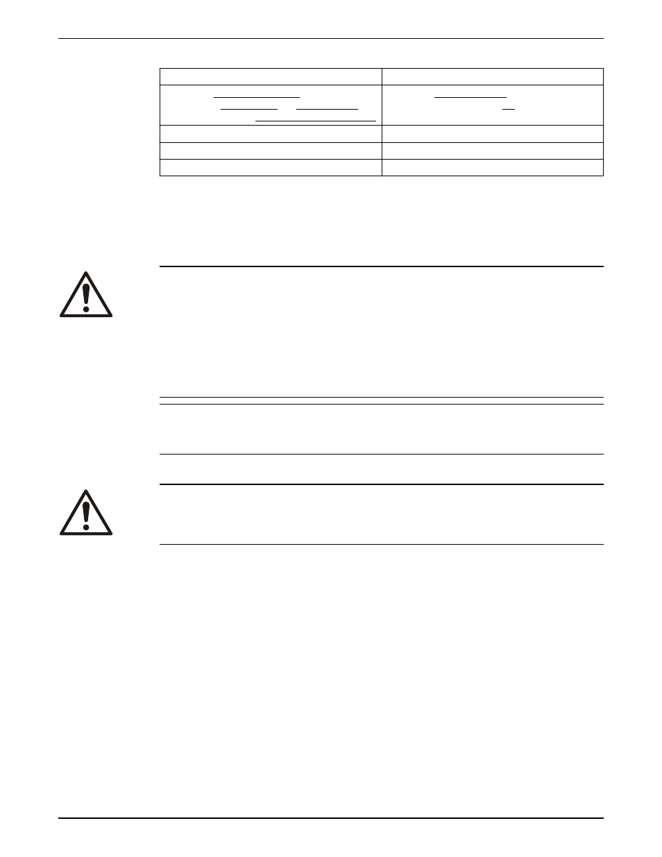
Specifications — grease types
Polyurea-based greases
Lithium-based greases, NLGI 2
Pumps built on or after Dec 1, 2014 use Polyurea-based
greases. See date code label and lubrication label on
pump or bearing frame indicating polyurea-base grease
Pumps built before Dec 1, 2014 were built with Lithium-
based greases, NLGI 2, and do not have lubrication label
on pump or bearing frame indicating pump grease type
ExxonMobil Polyrex
TM
EM
Shell Gadus
®
S2 V100 2 (was Alvania RL 2)
Chevron SRI NLGI 2
Chevron Multifak
®
EP 2
Shell Gadus
®
S5 T100 2
ExxonMobil Unirex
TM
N2
Disassembly
Disassembly precautions
This manual clearly identifies accepted methods for disassembling units. These methods
must be adhered to.
WARNING:
• Make sure that the pump is isolated from the system and that pressure is relieved
before you disassemble the pump, remove plugs, open vent or drain valves, or
disconnect the piping.
• Always disconnect and lock out power to the driver before you perform any
installation or maintenance tasks. Failure to disconnect and lock out driver power will
result in serious physical injury.
• Crush hazard. The unit and the components can be heavy. Use proper lifting methods
and wear steel-toed shoes at all times.
NOTICE:
Make sure that all replacement parts are available before you disassemble the pump for
overhaul.
Drain the pump
CAUTION:
• Allow all system and pump components to cool before you handle them to prevent
physical injury.
1. Close the isolation valves on the suction and discharge sides of the pump.
You must drain the system if no valves are installed.
2. Open the drain valve.
Do not proceed until liquid stops coming out of the drain valve. If liquid continues to
flow from the drain valve, the isolation valves are not sealing properly and you must
repair them before you proceed.
3. Leave the drain valve open and remove the drain plug located on the bottom of the
pump housing.
Do not reinstall the plug or close the drain valve until the reassembly is complete.
4. Drain the liquid from the piping and flush the pump if it is necessary.
5. Disconnect all auxiliary piping and tubing.
Remove the hex coupling guard
1. Remove the two capscrews that hold the outer (motor side) coupling guard to the
support brackets.
2. Spread the outer guard apart and pull it off the inner guard.
Maintenance
28
Series 1510 Installation, Operation, and Maintenance Manual