Align the rexnord®omega® coupling, Align the rexnord, Omega – Bell & Gossett P81673 REV I Series 1510 User Manual
Page 21: Coupling
P
A
R
1
1
2
3
A
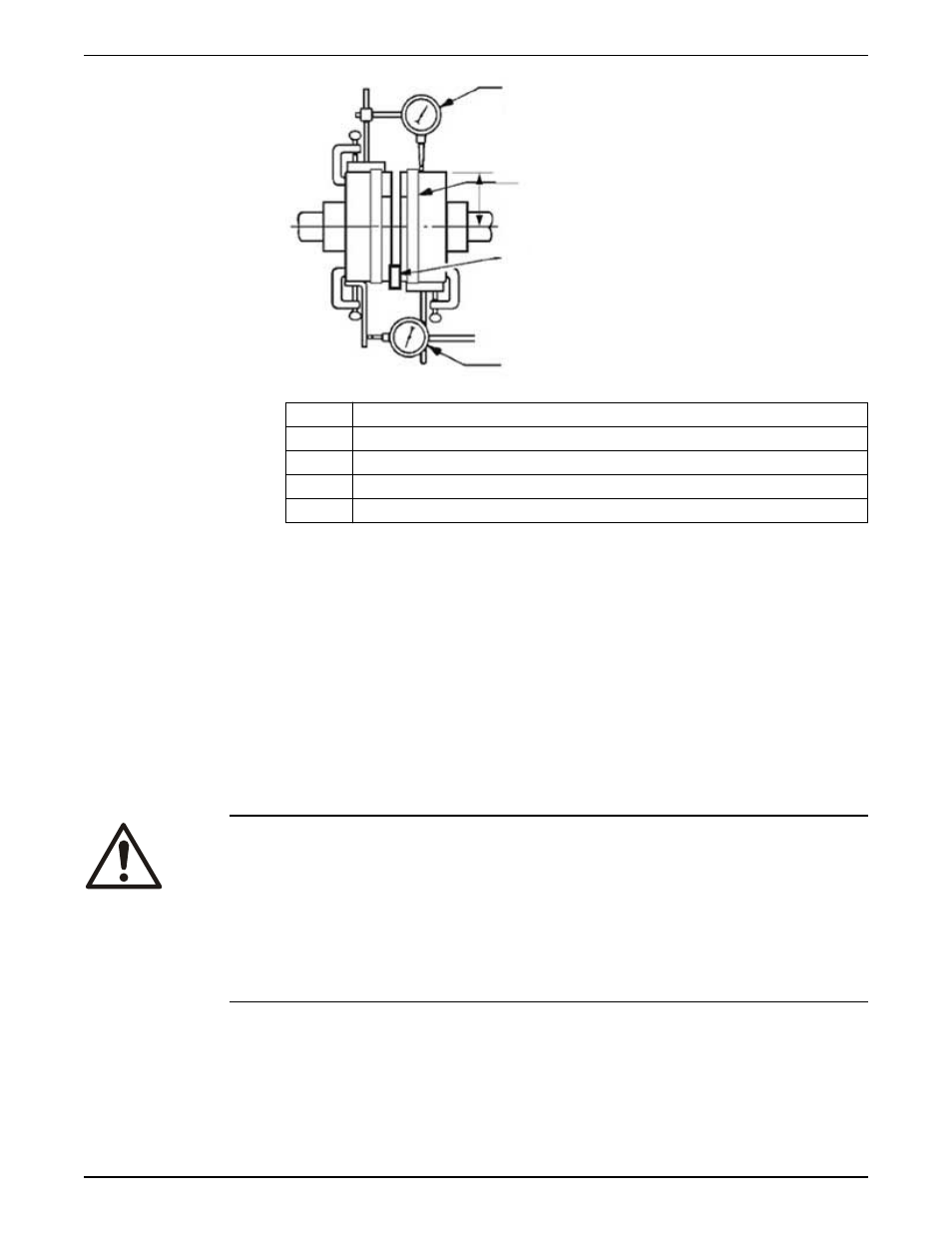
Angular alignment
P
Parallel alignment
1
Dial indicators
2
Index line
3
Resilient separator
d) Set the dial to zero.
e) Rotate both coupling halves together and make sure that the index lines remain
matched.
f)
Reposition the equipment until the offset is within the permissible value.
2. Check the parallel misalignment:
a) Mount the dial indicator base to one coupling half, or shaft.
b) Position the dial indicator button on the outside diameter of the opposite
coupling half.
c) Set the dial to zero.
d) Rotate both coupling halves together and make sure that the index lines remain
matched.
e) Reposition the equipment until the offset is within the permissible value.
Align the Rexnord
®
Omega
®
coupling
WARNING:
• Install coupling capscrews and setscrews using either a torque wrench or another
torque measuring device. Hardware that is not installed per the listed torque values
can become loose and dislodge from the coupling assembly. Failure to follow these
instructions can result in serious personal injury or death, or property damage.
• Do not use capscrews with damaged or absent thread lock coating. Otherwise, you
do not achieve the required counterforce and the hardware can become loose and
dislodge from the coupling assembly. Failure to follow these instructions can result in
serious personal injury or death, or property damage.
1. Recheck the hubs to be certain that both the angular and parallel alignments are still
within the proper range.
2. Loosen the setscrew on the pump hub.
3. Torque all element and high speed ring capscrews to the values shown in Fastener
torque values and maximum RPM for Rexnord Omega couplings.
If possible, recheck angular and parallel alignments.
4. Loosely install one half of the coupling opposite the hub setscrews.
Installation
Series 1510 Installation, Operation, and Maintenance Manual
19