Maximum number of devices in a rs485 bus, Grounding / common wire, Connections – NOVUS RS422 Basics User Manual
Page 4
RS485 & RS422 Basics
NOVUS PRODUTOS ELETRONICOS LTDA www.novusautomation.com
4/6
MAXIMUM NUMBER OF DEVICES IN A RS485 BUS
RS485 standard does not specify the maximum number of devices attached to a bus, but it does a lot of parameters that
can be used for calculating this limit. Some of these parameters are:
•
Low limit for bus resulting load resistance.
•
Load (resistance) value that each device presents to the bus, called “Unit Load” (15 k
Ω
).
•
Minimum current value that the driver (transmitter) of a RS485 device must be able to supply.
Based on these data and considering the need of termination resistors in both ends of the bus (corresponding to 60
Ω
), it
can be calculated the limit of 32 unit load devices for a RS485 communication bus.
Many new RS485 devices have less than one unit load, usually 1/2, 1/4 and 1/8 of a unit load. By using only 1/8
th
load
devices in a network, it is possible to have up to 256 devices in a terminated RS485 bus.
In smaller applications, where the cable lengths are short and/or the data rate is low, it may be possible to eliminate the
termination resistors. This allows the bus device capacity to increase from 32 to 282 devices! Of course, a reliable
operation in such condition is not guaranteed at all.
GROUNDING / COMMON WIRE
This topic is the least understood issue in RS485 networking, and cause of most failures and communication errors. Data
in differential communication lines is transmitted as a potential difference between the 2 wires of a twisted pair. Binary
data is represented as a positive or negative voltage difference between the 2 wires. The voltage difference between any
of the wires to a common reference is not important, if maximum limits are respected. This allows that distinct systems
communicate even when no common potential is established.
Transmitters and receivers may get damaged if high voltage is applied from any of the wires to a common reference
(ground). TIA/EIA-485 specifies this maximum common-mode voltage from –7 V to +12 V, while TIA/EIA-422 specifies
limits from –7 V to +7 V. Voltage above these limits are usual when only the communication pair connects multiple
isolated devices.
Proper grounding of the networked devices may help, but don’t always solve the problem. In a typical industrial
installation, ground potential difference in two locations may be of many volts, rising to hundreds of volts during lightning.
The best solution to avoid damage to communication circuits is the use of an additional wire that interconnects all
common terminals (ground) of the networked devices.
Use of shielded cable is recommended when cable cost is not an important issue. A properly grounded shielded cable
has high noise immunity against external interference (EMI), even when the cable is close to electrical interference
sources like frequency inverters, weld machines, contactor coils and AC power cables.
To reduce cabling costs, a non-shielded twisted pair cable may be used, but it should be installed away from these EMI
sources.
CONNECTIONS
The appropriate connection of the devices depends on the type of serial network: RS422, 2-wire RS485 or 4-wire RS485.
A shielded twisted-pairs cable is recommended for wiring the communication bus from the converter to all network
devices. The shield should be grounded and/or connected to the common terminals of all devices. The minimum
recommended wire gauge is 24 AWG (0.2 mm
2
).
Use of a wire connecting all devices common terminals is highly recommended. Damage of the networked
devices may result if this recommendation is not followed.
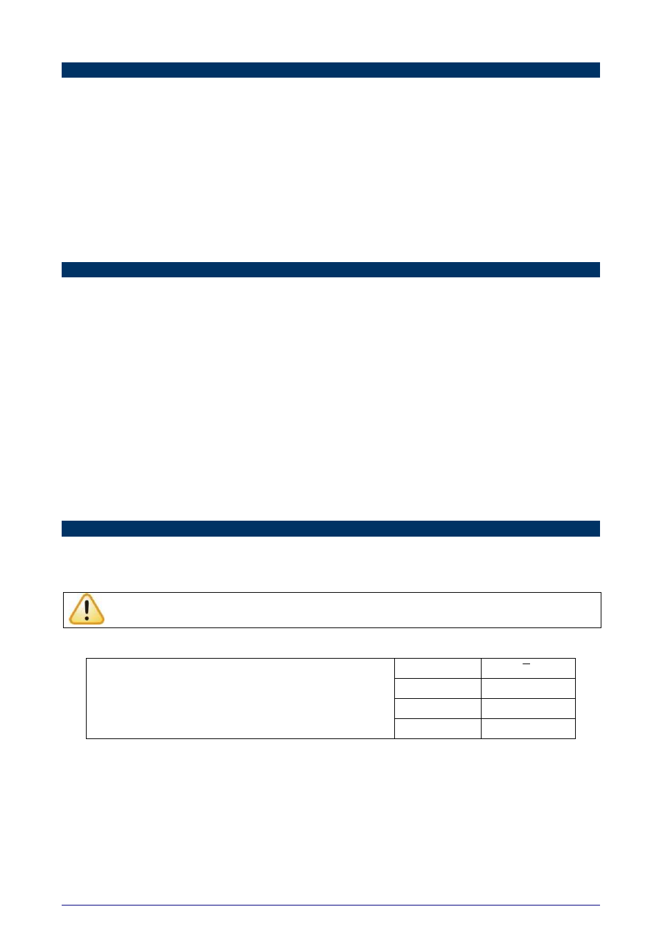
RS485 or RS422 devices from different vendors or of different models may identify the communication terminals using
distinct notation. The following table shows some of these notations and its equivalences.
D
D
D1
D0
B
A
POPULAR RS485 AND RS422 CONNECTION IDENTIFICATION
D+
D-
HALF-DUPLEX RS485 (2 WIRES)
This is the usual RS485 connection. A single twisted pair is used for data transmission and reception. Multiple RS485
devices are connected in a single bus, as shown in the next figure. Devices from different vendors may use different
names for the data signal terminals. In the following figure, different identification schemes are presented for each
device.