Appendix 1 – serial communication protocols – NOVUS myPCLab EN User Manual
Page 8
myPCLab
NOVUS AUTOMATION
8/9
APPENDIX 1 – SERIAL COMMUNICATION PROTOCOLS
Each myPCLab module installed in a PC is accessible as a distinct serial COM port. A module can communicate in one
of two protocols: ASCII (delimited text) or Modbus RTU. Any program with serial communication capability using one of
these protocols may be used to gather measurement data from the modules.
The used communication protocol depends on the “auto-send” module configuration. See the software help for
information on how the change the “auto-send” configuration.
•
Auto-send disabled: Communicates using Modbus RTU protocol. The module is a slave that responds to read
requests issued by a Modbus master (for example a SCADA software).
•
Auto-send enabled: Communicates using ASCII (delimited text) protocol. The module transmits continuously the
values measured in its channels, in text format.
The module can only be configured using the myPCLab software.
The serial COM port assigned to a device will only be available a few seconds after connection of the
myPCLab module to a USB port, since Windows operating systems needs to load the appropriate drivers.
To check the COM port assigned to each module, use the myPCLab software or go to the Windows
Control Panel in:
Control Panel/System/Hardware/Device Manager/Ports (COM & LPT)
MODBUS RTU (AUTO-SEND MODE DISABLED)
myPCLab is a Modbus RTU slave that can answer to “Read Holding Register” requisitions, Modbus command number
3. The module doesn’t have a specific Modbus address, since it’s the only device in its serial port. It will answer to read
request to any valid slave address.
When configuring the serial communication parameters of the Modbus master, set the COM port number assigned to the
device. The USB port ignores all other serial communication parameters.
•
Communication Port: Select the COM port number assigned to the myPCLab.
•
Baud rate: any
•
Number of data bits: any
•
Stop bits: any
•
Parity: any
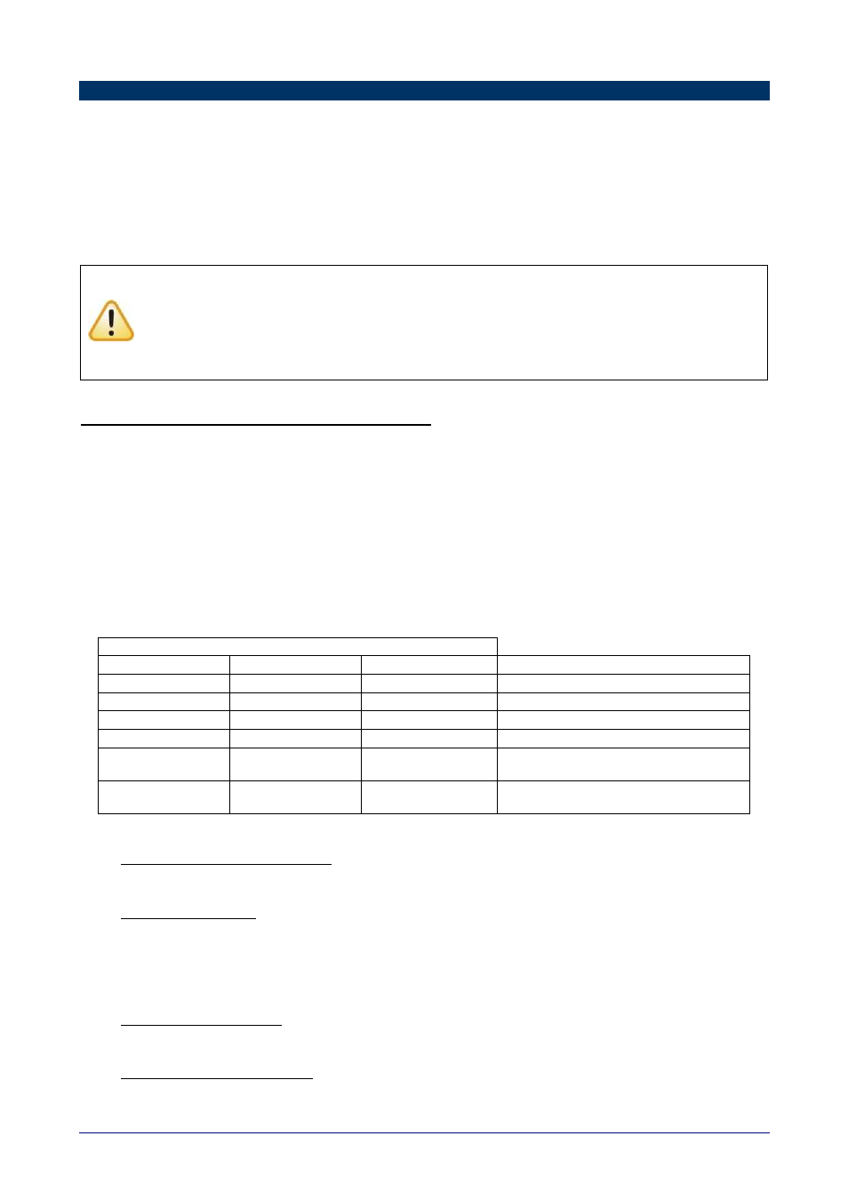
The following table shows the Modbus registers available for reading. Three different address formats are presented.
Use the address format according to your Modbus master.
Modbus Address (in 3 different formats)
Protocol, 0 based
Protocol, 1 based
PLC
Content
3
4
40004
Channel 3 (digital input) current state
4
5
40005
Channel 1 value
5
6
40006
Channel 2 value
6
7
40007
Ambient temperature value
62
63
40063
Counting/Timing/Frequency value (high
word)
63
64
40064
Counting/Timing/Frequency value (low
word)
Holding Registers Table (reference 4X)
•
Channel 3 (digital input) current state
Value that represents the current state of the digital input. The values associated to levels ‘0’ and ‘1’ are defined
in the module configuration.
•
Channel 1 and 2 values
Current value of the input channel, in engineering units. For values with decimal places, the decimal point
separator will be omitted. Example: A channel with value 13.96 will be read as 1396.
Measured values above or below its specified limits will be replaced by the corresponding overflow or underflow
values, according to the module configuration.
A disabled channel will return 0 (zero) as its measured value.
•
Ambient Temperature Value
Current measurement from the internal ambient temperature sensor, in degrees Celsius or Fahrenheit, according
to module configuration. The decimal point separator is omitted. Example: 23.8°C is read as 238.
•
Counting/Timing/Frequency value
Together, they have the current counting, timing or frequency value, depending on the configuration. When
directly read, this value is not multiplied by the scale factor.