NOVUS N440 User Manual
Page 2
LEVEL 2 –OUT2 SET POINT
(Available only on models with 2 outputs).
SP2
SP2
SP2
SP2
Set Point 2
Temperature set point associated to the OUT1 output. Possible
values are limited by the parameters
SPL
SPL
SPL
SPL e SPk
SPk
SPk
SPk in level 3
LEVEL 3 – PARAMETERS CONFIGURATION
Ac1
Ac1
Ac1
Ac1
Action 1
OUT1 Functions:
0
00
0
Reverse action usually used for heating
1
11
1
Direct Action usually used for cooling.
2
22
2
Low temperature alarm
3
33
3
High temperature alarm
4
44
4
Low temperature alarm with initial blocking
5
55
5
High temperature alarm with initial blocking
6
66
6
Out of range alarm (differential).
7
77
7
In range alarm (differential).
8
88
8
Out of range alarm with initial blocking.
9
99
9
In range alarm with initial blocking.
See the following section for details.
Ac2
Ac2
Ac2
Ac2
Action 2
OUT2 Functions:
0
00
0
Reverse action usually used for heating
1
11
1
Direct Action usually used for cooling.
2
22
2
Low temperature alarm
3
33
3
High temperature alarm
4
44
4
Low temperature alarm with initial blocking
5
55
5
High temperature alarm with initial blocking
6
66
6
Out of range alarm (differential).
7
77
7
In range alarm (differential).
8
88
8
Out of range alarm with initial blocking.
9
99
9
In range alarm with initial blocking.
See the following section for details.
ky1
ky1
ky1
ky1
Histeresis 1
OUT1 Hysteresis: Defines the differential range between the
temperature value at which the alarm is turned on and the value at
which it is turned off (in engineering units - °C or °F). Adjustable in
the range 0.1 to 70.
ky2
ky2
ky2
ky2
Histeresis 2
OUT2 Hysteresis: Defines the differential range between the
temperature value at which the alarm is turned on and the value at
which it is turned off (in engineering units - °C or °F). Adjustable in
the range 0.1 to 70.
ofs
ofs
ofs
ofs
Offset
Offset value to be added to the measured temperature to
compensate sensor error. Default value: zero. Range: –15 to +15.
spl
spl
spl
spl
SP Low Limit
Set point Low Limit: sets the minimum value allowed for the set
points 1 and 2.
Spl
Spl
Spl
Spl< spK
spK
spK
spK
spK
spK
spK
spK
SP High Limit
Set point High Limit: sets the maximum value allowed for the set
points 1 and 2.
Spx
Spx
Spx
Spx > spl
spl
spl
spl
Unt
Unt
Unt
Unt
Unit
Selects the display indication to be in ºC or ºF.
0
00
0 Temperature in degrees Celsius.
1
11
1 Temperature in degrees Fahrenheit.
prt
prt
prt
prt
Protection
Configuration protection:
0
No protection
1
No access to the Calibration level;
2
No access to Calibration and Configuration levels;
3
No access to Calibration, Configuration and SP2 levels;
4
No access to Calibration, Configuration, SP2 and SP1 levels;
LEVEL 4 – CALIBRATION
(al
(al
(al
(al
CAlibration Low
INPUT LOW CALIBRATION: Sets the Process Variable low calibration
(offset). Several keystrokes at
or
might be necessary to
increment one digit. The displayed value corresponds to the actual
(calibrated) temperature as seen by the controller.
(Ak
CAlibration High
INPUT HIGH CALIBRATION: Adjusts the Process Variable span
calibration (gain).
(jl
Cold Junction Low
Calibration
COLD JUNCTION OFFSET CALIBRATION: Adjusts the offset of the
cold junction temperature. Valid for thermocouple inputs only.
USING THE CONTROLLER
When in the process, the N440 displays the temperature measured by the sensor
connected in the terminals named SENSOR INPUT.
The sensor is defined at the purchase. The user needs then to configure outputs OUT1
and OUT2 (OUT2 is optional) with the desired functionality. Parameters
Ac1
Ac1
Ac1
Ac1 and Ac2
Ac2
Ac2
Ac2
define the outputs working mode. OUT1 is normally used as the control output,
whereas OUT2 is used as the alarm output. Depending on output requirements (relay
or logic pulse), the outputs may be configured differently.
The OUT1 e OUT2 outputs can perform in the following ways:
0
00
0- Reverse action usually used for heating.
Output turns on when temperature is bellow set point minus hysteresis. Output
turns off when temperature is above set point.
1
11
1- Direct Action usually used for cooling.
Output turns on when temperature is above set point plus hysteresis Output turns
off when temperature is bellow set point.
2
22
2- Low temperature alarm.
Output turns on when temperature is bellow set point. Output turns off when
temperature is above set point plus hysteresis.
3
33
3- High temperature alarm.
Output turns on when temperature is above set point. Output turns off when
temperature is bellow set point minus hysteresis.
4
44
4- Low temperature alarm with initial blocking.
Same as low temperature alarm, but with initial blocking as described next.
5
55
5- Low temperature alarm with initial blocking.
Same as high temperature alarm, but with initial blocking as described next.
6
66
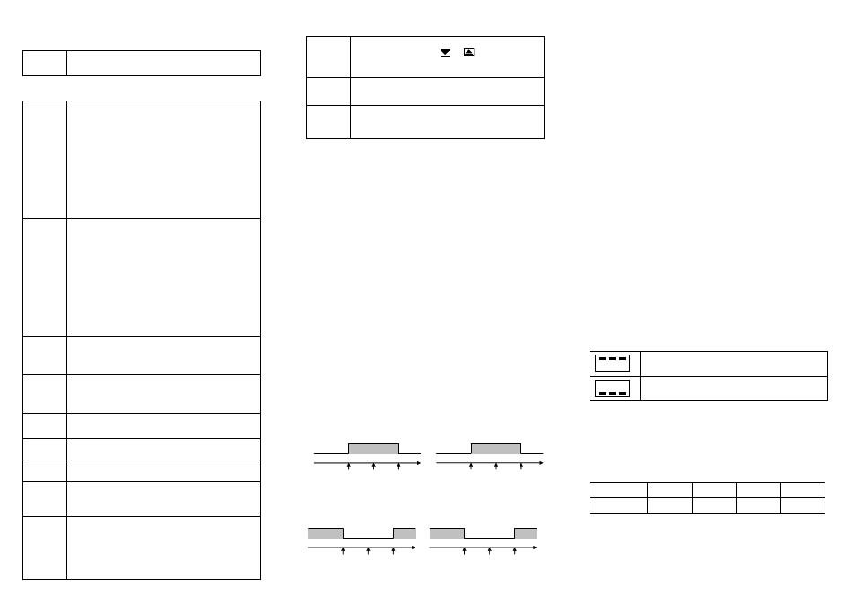
6- In range alarm (differential).
Available only for OUT2. Output turns on when temperature is in the range from
(
SP1
SP1
SP1
SP1
- SP2
SP2
SP2
SP2) to (SP1
SP1
SP1
SP1 + SP2
SP2
SP2
SP2).
SP2 – SP1
SP2 + SP1
SP2
OUTPUT ON
TEMPERATURE
OUT
SP1 - SP2
SP1 + SP2
SP1
OUTPUT ON
TEMPERATURE
ON
OUT1 programmed for in of range alarm
OUT2 programmed for in of range alarm
7
77
7- Out of range alarm (differential).
Available only for OUT2. Output turns on when temperature is out of the range from
(
SP1
SP1
SP1
SP1 - SP2
SP2
SP2
SP2) to (SP1
SP1
SP1
SP1 + SP2
SP2
SP2
SP2).
SP2 – SP1
SP2 + SP1
SP2
OUTPUT ON
TEMPERATURE
OUT
OUTPUT ON
SP1 - SP2
SP1 + SP2
SP1
OUTPUT ON
TEMPERATURA
OUT
OUTPUT ON
OUT1 programmed for out of range alarm
OUT2 programmed for out of range alarm
8
88
8- In range alarm with initial blocking.
Same as in range alarm, but with initial blocking as described next.
9
99
9- Out of range alarm with initial blocking.
Same as out of range alarm, but with initial blocking as described next.
Note 1: OUT1 and OUT2 outputs can’t be simultaneously configured for In Range and
Out of Range alarm.
Note 2: The initial blocking feature, when enabled, results in the controller ignoring
alarm conditions which exists when the controller is powered-on or started.
Alarms with initial blocking:
The initial blocking option inhibits the alarm from being recognized if an alarm condition
is present when the controller is first energized. The alarm will actuate only after the
occurrence of a non alarm condition followed by a new occurrence for the alarm.
In the front panel, OUT indicator will light on when OUT1 is active, and AL1 indicator
will light on when OUT2 is active.
Hysteresis parameters
ky1
ky1
ky1
ky1 and ky2
ky2
ky2
ky2 are associated to outputs OUT1 and OUT2,
and defines the differential range between the temperature value at which the alarm is
turned on and the value at which it is turned off
Offset (
ofs
ofs
ofs
ofs) parameter may be adjusted to correct temperature indication due to
sensor error. The adjusted value is added to the temperature read before indication.
Parameters write protection:
Write to parameters may be disabled for each parameter level by means of an internal
protection strap key which when ON will block access to configuration. The instrument
is not protected with the strap key in OFF position. By placing the strap at ON, access
will be limited as defined in the “
Prt
Prt
Prt
Prt’’ parameter description.
The protection parameter “
Prt
Prt
Prt
Prt” must be defined with the strap key in place otherwise
it cannot be changed.
PROBLEMS WITH THE CONTROLLER
Connection and configuration errors state for most of the problems in using the
controller. A final revision of parameters will save time and further losses. Error
messages are displayed to help the user to identify possible problems. If one of the
messages bellow is displayed, all outputs are turned off for safety.
•
Temperature above high limit.
•
Broken sensor. Pt100 badly connected
•
Temperature bellow low limit.
•
Pt100 short-circuited.
TECHNICAL ASSISTANCE
If you encounter a problem with your controller, review the configuration with regard to
inputs, outputs, alarms, etc. If the problem persists, contact your supplier or Novus at
[email protected].
ORDERING INFORMATION:
N440 -
J
R
R
- 24V
A
B
C
D
E
A. Series model: N440;
B. Input sensor: C (Pt100), J (type J thermocouple) or K (type K thermocouple);
C. Output 1:
R (Relay);
D. Output 2:
R (Relay) or P (Pulse);
E. Voltage rating: blank (100-240 Vac or 24V (24 Vac/dc);