NOVUS N1200 User Manual
N1200
1
N1200
Communication Protocol – V10x
1. SERIAL COMMUNICATION
1.1 COMMUNICATION INTERFACE
The optional serial interface RS485 allows to address up to 247 controllers in a
network communicating remotely with a host computer or master controller.
RS485 Interface
•
Compatible line signals with RS485 standard
•
2 wire connection from master to up to 31 slaves indicators in a multidrop bus. It
is possible address 247 nodes with multiple outputs converters.
•
Maximum communication distance: 1000 meters
•
The RS485 signals are:
D1 = D:
Bidirectional data line.
D0 =
D:
Bidirectional inverted data line.
C = GND:
Optional connection which left communication better.
General Characteristics
•
Optically isolated serial interface
•
Programmable baud rate: 1200, 2400, 4800, 9600, 19200, 38400, 57600 or
115200 bps.
•
Data Bits: 8
•
Parity: None, Even or Odd.
•
Stop Bits: 1
Communication Protocol
The MOSBUS RTU slave is implemented, available in most SCADA softwares in the
market.
All configurable parameters can be accessed (for reading or writing) through the
Registers Table. Broadcast commands are supported as well (address 0).
The available Modbus commands are:
03 - Read Holding Register
05 - Force Single Coil (Force Digital Output state)
06 - Preset Single Register
16 - Preset Multiple Registers (Block write to multiple holding registers)
The registers are arranged in a table in such a way that several registers can be
read in the same request.
1.2 CONFIGURATION OF SERIAL COMMUNICATION PARAMETERS
Two parameters must be configured in the device for serial communication:
bavd
bavd
bavd
bavd
: Baud rate. All devices with same baud rate.
addr
addr
addr
addr
: Device communication address. Each device must have an exclusive
address.
prty
prty
prty
prty
: Paraty.
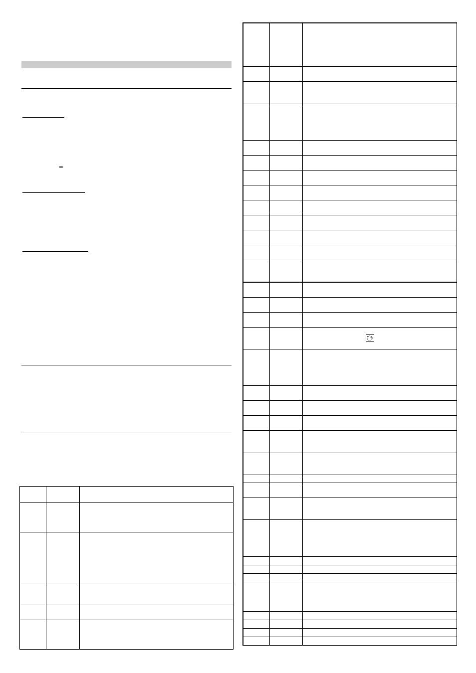
1.3 REGISTERS TABLE
Equivalent to the registers referenced as 4XXXX.
The holding registers are basically a list of the internal indicator parameters. All
registers above address 12 can be read or written. The registers up to this address
in more are read only. Please verify each case. Each table parameter is a 16 bits
two complement signed word.
Holding
Registers
Parameter
Register Description
0000
Active SP
Read: Active control SP (main SP, from ramp and soak or
from remote SP).
Write: to main SP
Range: from
spll
spll
spll
spll
to
spkl
spkl
spkl
spkl
.
0001
PV
Read: Process Variable.
Write: Not allowed.
Range: Minimum value is the one configured in
spll
spll
spll
spll
and
the maximum value is the one configured in
spkl
spkl
spkl
spkl
. Decimal
point position depends on
dppo
dppo
dppo
dppo
value.
In case of temperature reading, the value read is always
multiplied by 10, independently of
dppo
dppo
dppo
dppo
value.
0002
MV
Read: Output Power in automatic or manual mode.
Write: Not allowed. See address 28.
Range: 0 to 1000 (0.0 to 100.0%).
0003
Remote
SP type
Read/Write: Selected input type for remote SP.
Range: 0 to 3
0004
Display
value
Read: Current value shown on display.
Write: Current value shown on display.
Range: -1999 to 9999. The range depends on the
displayed parameter.
0005
Prompt
index
Read: Current prompt position in the parameters flowchart.
Write: not allowed. Range: 0000h to 060Ch
Prompt number format: XXYYh, where:
XX
→
menu
cycle
number
(check
item
4
-
INSTALLATION/CONNECTIONS)
YY
→
prompt number (index).
0006
Status
Word 1
Read: Status bits. See table 2.
Write: not allowed.
0007
Software
Version
Read: The firmware version of controller. If V1.00, the read
value will be 100.
Write: not allowed.
0008
ID
Read: controller identification number.
Write: not allowed.
Values:
1 – N1100; 2 - N2000; 3 - N1500; 48 - 1200
Other values: special instruments.
0009
Status Word
2
Read: Status bits. See table 2.
Write: not allowed.
0010
Status Word
3
Read: Status bits. See table 2.
Write: not allowed.
0011
Ir
Ir
Ir
Ir
Integral Rate (in repetitions/min)
Range: 0 to 9999 (0.00 to 99.99)
0012
D
D
D
Dt
t
t
t
Derivative Time (in seconds). Range: 0 to 3000 (0.0 to
300.0)
0013
P
P
P
Pb
b
b
b
Proportional Band (in percentage)
Range: 0 to 5000 (0.0 to 500.0)
0014
tbas
tbas
tbas
tbas
Read/Write: Time base for the ramp and soak programs.
Range: 0 – 1 (seconds/minutes)
0015
C
C
C
Ct
t
t
t
Cycle Time (PWM, in seconds)
Range: 5 to 1000 (0.5 to 100.0)
0016
Freq
Freq
Freq
Freq
Read/Write: Mains frequency.
Range: 0 – 1 (60/50Hz)
0017
kyst
kyst
kyst
kyst
On/Off Control Hysteresis (in selected type engineering
unit).
Range: 0 to
spkl
spkl
spkl
spkl
-
spll
spll
spll
spll
0018
fltr
fltr
fltr
fltr
Read/Write: PV digital filter gain.
Range: 0 – 20
0019
ovll
ovll
ovll
ovll
Output Low Limit (minimum output power)
Range: 0 to 1000 (0.0 to 100.0%).
0020
ovkl
ovkl
ovkl
ovkl
Output High Limit (minimum output power)
Range: 0 to 1000 (0.0 to 100.0%).
0021
AvEn
AvEn
AvEn
AvEn
N2000 only.
Auto/Man key Enable –
.
1
Key enabled 0
Key disabled
0022
f.fvnc
f.fvnc
f.fvnc
f.fvnc
N2000 only.
F key function.
0
Not used.
7
Controller start/stop.
8
Select remote SP.
9
Ramp and soak hold.
10
Enable ramp and soak profile 1.
0023
Serial
number H
Serial Number High (Upper display).
Range: 0 to 9999. Read only
0024
Serial
number L
Serial Number Low (Lower display).
Range: 0 to 9999. Read only
0025
SV
Control Setpoint (Prompt Setpoint).
Range: from
spll
spll
spll
spll
to
spkl
spkl
spkl
spkl
.
0026
spll
spll
spll
spll
Setpoint Low limit.
Range: minimum value depends on the input type selected
in
type
type
type
type
(see Table 1) to
spk
spk
spk
spkl
l
l
l
.
0027
spkl
spkl
spkl
spkl
Setpoint High limit.
Range: minimum value is
spll
spll
spll
spll
and maximum depends on
the input type selected in
type
type
type
type
(see Table 1).
0028
Reserved Internal use.
0029
offs
offs
offs
offs
PV offset
Range: from
spll
spll
spll
spll
to
spkl
spkl
spkl
spkl
.
0030
dppo
dppo
dppo
dppo
PV decimal point position
Range: 0 to 3
0
→
0.000; 1
→
00.00; 2
→
000.0; 3
→
0000
0031
Sp.a1
Sp.a1
Sp.a1
Sp.a1
Alarm 1 Setpoint.
Range: The minimum value is at
spll
spll
spll
spll
for non-differential
alarm or
spll
spll
spll
spll
-
splk
splk
splk
splk
for differential alarm
The maximum value is at
spkl
spkl
spkl
spkl
for non-differential alarm or
at
spkl
spkl
spkl
spkl
-
spll
spll
spll
spll
for differential alarm.
0032
Sp.a2
Sp.a2
Sp.a2
Sp.a2
Alarm 2 Setpoint. Range: same as in
spa1
spa1
spa1
spa1
.
0033
Sp.a3
Sp.a3
Sp.a3
Sp.a3
Alarm 3 Setpoint. Range: same as in
spa1
spa1
spa1
spa1
.
0034
Sp.a4
Sp.a4
Sp.a4
Sp.a4
Alarm 4 Setpoint. Range: same as in
spa1
spa1
spa1
spa1
.
0035
Fva1
Fva1
Fva1
Fva1
Alarm 1 Function. Range: 0 to 8
0
→
off
off
off
off
; 1
→
ierr
ierr
ierr
ierr
; 2
→
rs
rs
rs
rs
; 3
→
rfai
rfai
rfai
rfai
;
4
→
lo
lo
lo
lo
; 5
→
ki
ki
ki
ki
; 6
→
difl
difl
difl
difl
; 7
→
difk
difk
difk
difk
;
8
→
dif
dif
dif
dif
.
0036
Fva2
Fva2
Fva2
Fva2
Alarm 2 Function. Range: same as in
fua1
fua1
fua1
fua1
.
0037
Fva3
Fva3
Fva3
Fva3
Alarm 3 Function. Range: same as in
fua1
fua1
fua1
fua1
.
0038
Fva4
Fva4
Fva4
Fva4
Alarm 4 Function. Range: same as in
fua1
fua1
fua1
fua1
.
0039
Kya1
Kya1
Kya1
Kya1
Alarm 1 Hysteresis. Range: 0 to 9999 (0.00 to 99.99%)