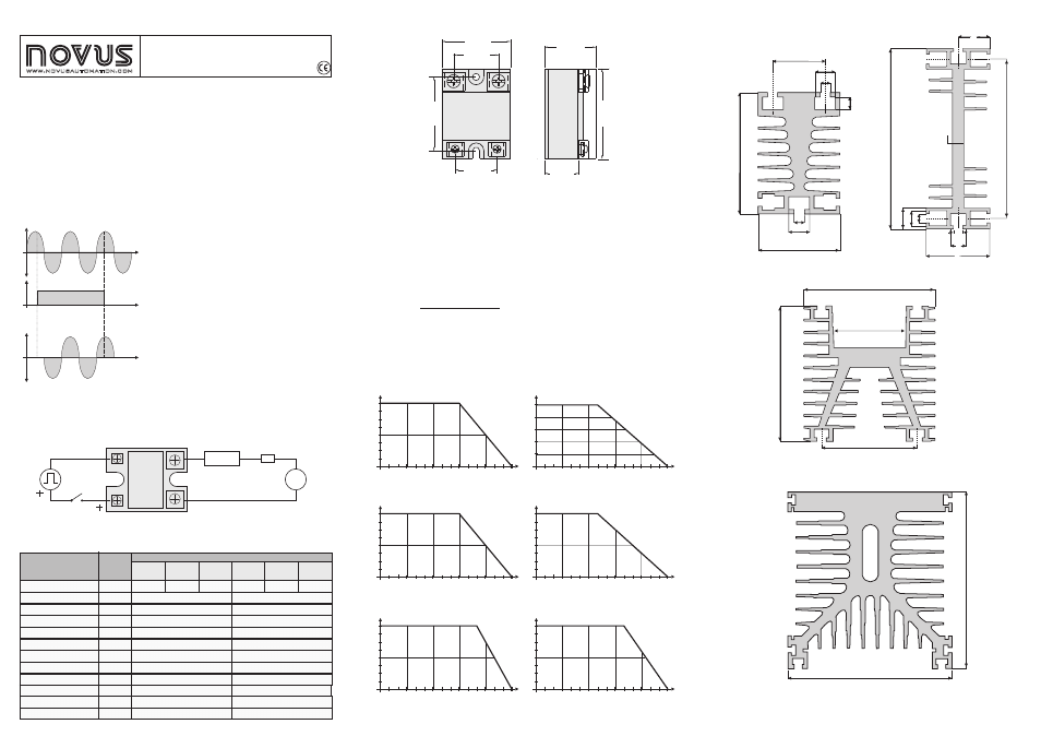
NOVUS SSR10,25,40,60,80E 100 A User Manual
75°c - t r, Il x v
Model
Parameter
Unit
SSR 2510
SSR 4810
SSR 2525
SSR 4825
SSR 2540
SSR 4840
SSR 4860
SSR 4880
SSR 48100
Load current ( )
Load voltage
IL
Turn-on voltage (
)
Leakage current
Frequency
dv/dt
Control voltage
Control current
Switching time
Control method
Isolamento
Operating temperature
Vssr
A rms
V rms
V rms
mA rms
Hz
V/µs
Vcc
mAcc
ms
V rms
°C
10
40
25
50 a 250 (25XX) / 75 a 480 (48XX)
< 5 (25XX) / < 14 (48XX)
1,1 a 1,5
47 a 70
50 a 200
4 a 32
5 a 12
<10
Zero cross trigger
4000
-30 a 80
60
100
80
40 a 480
1,6 a 1,8
<5
47 a 63
300
3 a 32
6 a 25
<10
Zero cross trigger
2000
-40 a 80
FEATURES
The Solid State Relays (SSR) are electronic devices used for switching resistive or inductive AC loads
with many advantages over the conventional relays.
Increased lifetime, due to the fact that there are no moving parts, and thus, no mechanical wear. Zero
cross switching, which implies lower electrical noise. Silent operation. Control INPUT signal optically
isolated from the OUTPUT. Internal snubber provided.
OPERATION
A control voltage applied to the device INPUT turns the SSR ON, energizing the load. The conduction
effectively occurs at the next zero crossing of the mains voltage. When the INPUT signal is removed,
the SSR turns OFF when the load reaches a current equal to zero. This means that the load switching
may be delayed by ½ of mains period (or 8.3 ms for the 60 Hz mains).
ELECTRICAL CONNECTIONS
The two connections needed for the installation of the SSR are the command signal and the load
circuit. The load circuit must be protected by an ultra-fast fuse with a rate that matches the SSR nominal
current specification. The SSR terminals must be firmly screwed and the wire gauge compatible with
the output load.
SPECIFICATIONS
Supply voltage
Control signal
Tensão sobre a carga
Turning the output ON and OFF only on the
mains voltage zero crossing brings important
performance advantages to the system:
practically no EMI is generated during the
load switching and the SSR is submitted to
less severe switching conditions.
On the
other hand, the SSR is suitable to AC loads
only (it cannot be used to switch DC loads).
The SSR control signal is indicated by a LED
on the SSR body.
For better heat transfer, a thermal conducting paste must be used between the SSR and the heat sink.
The SSR along with its heat sink must be mounted in a vertical position such as to allow for air flow and
thus a good heat exchange.
Where:
R
T
I
V
thha
amb
L
ssr
75°C
= Thermal resistance heat sink to ambient
= Maximum ambient temperature
= Load current
= Voltage drop when the SSR is ON.
is the maximum temperature allowed for the SSR.
75°C - T
R
=
thha
IL x V
ssr
amb
HEAT DISSIPATION
The SSR generates heat during its conduction. This heat must be dissipated to avoid SSR fail due to
over-heat. The nominal SSR load specification assumes the use of a suitable heat sink. Without a heat
sink the allowed load current is substantially reduced. The user may calculate the needed heat sink or
make use of a heat sink suggested by Novus.
Vac
LOAD
INPUT
LOAD
FUSE
SSR
SUPPLY
VOLTAGE
CONTROL SIGNAL
Fig 5 - SSR2540/4840 + sink
mm
ND40-100
Fig 6 - SSR4860 + sink
mm
NDP3-120
15°C
20 A
40 A
I
L
30°C
45°C
T
AMB
60°C
75°C
15°C
30 A
60 A
I
L
30°C
45°C
T
AMB
60°C
75°C
Fig 3 - SSR2510/4810 + sink
mm
ND10-65
Fig 4 - SSR2525/4825 + sink
mm
ND25-120
15°C
5 A
10 A
I
L
30°C
45°C
T
AMB
60°C
75°C
15°C
15 A
25A
I
L
30°C
45°C
T
AMB
60°C
75°C
5 A
Fig 7 - SSR4880 + sink
mm fun 3 m/s
NDP3-120
+
Fig 8 - SSR48100 + sink
mm fun 3
NDP3-120
+
m/s
15°C
40 A
80 A
I
L
30°C
45°C
T
AMB
60°C
75°C
15°C
50A
100A
I
L
30°C
45°C
T
AMB
60°C
75°C
29.0
27.0
47.5
44.0
33.0
22.0
58.0
42.0
10.5
6.5
10.5
27.0
62.0
5.2
5.2
116.0
64.0
85.0
125.0
14.5
10.5
6.5
1
10.5
8.0
22.2
44.5
10.5
6.5
Fig 9 - Sink ND10 (to 65 mm: R thha = 2.0 °C / W)
Fig 10 - Sink ND25 (to 120 mm: R thha = 1.1 °C / W) /WWwW)
Fig 11 - Sink ND40 (to 100 mm: R thha = 0.65 °C / W)
Fig 9 - Sink NDP3 (to 120 mm: R thha = 0.52 °C / W)
Fig 1 - Electrical connections
Fig 2 - Dimensions
SOLID STATE RELAY - SSR
10, 25, 40, 60, 80 E 100 A
INSTRUCTIONS MANUAL
www.novusautomation.com
135 mm
125 mm
Product sold by Novus Automation.
120