NOVUS TxIsoRail0 - 10Vdc User Manual
NOVUS Sensors
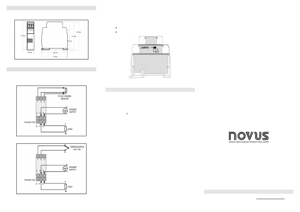
INSTALLATION
The transmitter is intended for DIN rail mounting. Its drawing is preseted in Figure
04.
Figure 04 – Transmitter dimensions
ELECTRICAL CONNECTIONS
Figure 5 below shows the transmitter connections to the sensor and power supply.
Terminals 1, 2 e 3 are used for sensor input. For 2-wire Pt100, terminals 2 and 3 shall
be connected together.
Figure 05 – Transmitter wiring – Pt100
Figure 06 – Transmitter wiring (Thermocouple, mA, Vdc)
The LOAD represents voltage metering instrument (indicator, controller, register,
etc.).
Electrical Connections – 0-10 Vdc input
For 0-10 Vdc input, the transmitter requires an internal hardware configuration change.
Please open the instrument case and change the jumper shown in Figure 07.
Position 1-2 : 0-10 Vdc input
Position 2-3 : al other input types (factory setting).
Figure 07 – Jumper position for 0-10 Vdc input
OPERATION
All input types and the 0-10 Vdc output are factory calibrated.
However, a manual offset trim is implemented to provide fine adjustments to the
signal in the field. This is accomplished by the front keys ZERO+ and ZERO-. Using a
small tool, press and hold the desired key for at least 2 seconds to increase or
decrease the output. The offset adjustment is capable of varying the output current by
an amount equal to 5 % relative to the original calibration.
The offset correction can also be accomplished by the TxConfig software. See in
Figure 3 the Zero Correction field for this purpose. The serial adaptor can be
connected to the transmitter while it is operating in the process.
The input types are listed in Table 1, along with the maximum and minimum ranges
accepted by each one. The TxConfig software will allow only configurations that are
consistent with the data in this table.
Please note that the specified accuracy is referenced to the maximum span of each
input type. For instance, for the Pt100 input, the 0.2 % accuracy results in 1.7 ºC total
accuracy [(650 – (-200)) x 0.2].
Note: when using a Pt100 simulator, make sure the transmitter Pt100 excitation
current (0.18 mA) is compatible with the simulator specification.
M I C R O P R O C E S S O R
B A S E D T E M P E R A T U R E T R A N S M I T T E R
T x I s o R a i l 0 - 1 0 V d c
I N S T A L L A T I O N A N D O P E R A T I N G M A N U A L
WARRANTY
Warranty conditions are available on our web sit
Man 5001522