Addr – NOVUS N322 User Manual
Page 2
of1
Off time 1
Off time 1 - Defines the minimum off time for control OUTPUT 1. Once
OUTPUT 1 is turned off, it remains so for at least the time programmed
in of1. For thermocouple inputs this parameter is not available. This
parameter is intended for refrigeration systems where longer
compressor life is desired. For heating systems, program of1 to zero.
Value in seconds, 0 to 999 s.
on1
on time 1
On time 1 - Defines the minimum on time for control OUTPUT 1. Once
turned on, OUTPUT 1 remains so for at least the time programmed in
on1
. For thermocouple inputs this parameter is not available. This
parameter is intended for refrigeration systems where increased
compressor life is desired. For heating systems, program on1 to zero.
Value in seconds, 0 to 999 s.
dl1
Delay 1
Delay 1 - Delay time to start control. Upon power-on, control OUTPUT 1 is
kept off until the time programmed in dl1 is elapsed. Its usage is
intended to prevent multiple compressors to start simultaneously after
the turn-on of a system with several controllers. Value in seconds, 0 to
250 s.
of2
Off time 2
Off time 2 - Defines the minimum off time for control OUTPUT 2. Once
OUTPUT 2 is turned off, it remains so for at least the time programmed
in of2. For thermocouple inputs this parameter is not available. This
parameter is intended for refrigeration systems where increased
compressor life is desired. For heating systems, program on2 to zero.
Value in seconds, 0 to 999 s.
on2
on time 2
On time 2 - Defines the minimum on time for control OUTPUT 2. Once
turned on, OUTPUT 2 remains so for at least the time programmed in
on2
. For thermocouple inputs this parameter is not available. This
parameter is intended for refrigeration systems where increased
compressor life is desired. Value in seconds, 0 to 999 s. For heating
systems, program of2 to zero.
dl2
Delay 2
Delay 2 - Delay time for OUTPUT 2 to turn on relative to OUTPUT 1.
This parameter defines a particular working mode, typically used in
multiple stage systems, where OUTPUT 2 is allowed to go on only if
OUTPUT 1 is already on for at least dL2 seconds. Also, OUTPUT 2 is
driven off whenever OUTPUT 1 goes off. dL2= 0 disables this
function. Value in seconds, 0 to 250 s.
Addr
Address
Address - Controllers with the optional RS485 Modbus RTU
communication interface have the Addr parameter at the Configuration
level. Set a unique Modbus address for each equipment connected to the
network. Address range is from 1 to 247.
Level 3 – Calibration level
The controller is factory calibrated. The following parameters should be accessed only
by experienced personnel. To enter this cycle, the
key must be kept pressed for 4
seconds.
Don’t press the
and
keys if you are not sure of the calibration
procedures. Just press the
key a few times until the temperature
measurement level is reached again.
pas
Password - Enter the correct password to unlock write operations for
the parameters in the following levels.
[Al
Calibration low - Offset value of the input. It adjusts the lower
measurement range of the sensor.
[Ak
Calibration High - Gain calibration. It adjusts the upper measurement
range of the sensor.
[JL
Cold Junction Offset calibration - This parameter is available only
for thermocouple.
FA(
Factory Calibration - Restores factory calibration parameters. Change
from 0 to 1 restores the calibration parameters with factory values.
Prt
Protection - Defines the levels of parameters that will be password
protected. See "Configuration Protection" for details.
Pa(
Password Change - Allows changing the current password to a new
one. Values from 1 to 999 are allowed.
Sn2
Serial number - First part of the controller electronic serial number.
sn1
Serial number - Second part of the controller electronic serial number.
sn0
Serial number - Third part of the controller electronic serial number.
WORKING WITH THE CONTROLLER
Multiple output controllers are suited for controlling multiple stage systems.
Other applications require OUTPUT 1 to be the control output and OUTPUT 2 to be the
alarm.
There are eight distinct alarm functions implemented in OUTPUT 2, selected by the
parameter Ac2, described below:
2
- Low temperature alarm – OUTPUT 2 is turned on when the measured
temperature falls below the SP2 value.
3
- High temperature alarm – OUTPUT 2 is turned on when the measured
temperature exceeds the value programmed in SP2.
4
- Inside range alarm – OUTPUT 2 is turned on when the measured
temperature is within the range defined by:
(SP1 – SP2) and (SP1 + SP2)
5
- Outside range alarm: OUTPUT 2 is turned on when the temperature falls
outside the range defined by:
(SP1 – SP2) and (SP1 + SP2)
Functions 6, 7, 8 e 9 are identical to the above ones except that they incorporate the Initial
Blocking feature, which inhibits the output if an alarm condition is present at start-up. The
alarm will be unblocked after the process reaches a non-alarm condition for the first time.
In a multiple stage application, SP1 and SP2 are configured to operate at different
temperatures, creating a progressive sequence for turning on the outputs
(compressors) in response to a system demand. The output delays for turning on the
compressors (dL1 and dL2) cause the compressors to be turned on one by one,
minimizing energy demand.
Another usage for multiple output controllers is in systems that require automatic
selection between cool and heat action. In these applications, one output is configured
as reverse action (heating) and the other as direct action (refrigeration). The output
status led P1 and P2 in the controller panel, signals when the control output in on.
CONFIGURATION PROTECTION
A protection system to avoid unwanted changes to the controller parameters
is implemented. The level of protection can be selected from partial to full. The following
parameters are part of the protection system:
Pas
When this parameter is presented, the correct password should be entered to
allow changes of parameters in the following levels.
Prt
Defines the level of parameters that will be password protected:
1 - Only calibration level is protected (factory configuration);
2 - Calibration and Configuration levels are protected;
3 - All levels are protected - calibration, Configuration and setpoints.
PA(
Parameter for definition of a new password. Since it is located in the calibration
level, can only be changed by a user that knows the current password. Valid
passwords are in the range 1 to 999.
Configuration protection usage
PAS
parameter is displayed before entering a protected level. If the correct password is
entered, parameters in all following levels can be changed. If wrong or no password is
entered, parameters in the following levels will be read only.
Important notes:
1- After five consecutive attempts to enter a wrong password, new tentative will be
blocked for the next 10 minutes. If the current valid password is unknown, the master
password can be used only to define a new password for the controller.
2 - The password for a brand new device is 111.
MASTER PASSWORD
The master password allows user to define a new password for the controller, even if
the current password is unknown. The master password is based in the serial number
of the controller, and calculated as following:
[ 1 ] + [ higher digit of SN2 ] + [ higher digit of SN1 ] + [ higher digit of SN0 ]
For example the master password for the device with serial number 987123465 is: 1 9 3 6
as follows: 1 + sn2= 987; sn1= 123; sn0= 465 = 1 + 9 + 3 + 6
How to use the master password:
1- Enter the master password value at PaS prompt.
2- Go to PA( parameter and enter the new password, which must not be zero (0).
3- Now you can use this new password to access all controller parameters with modify
rights.
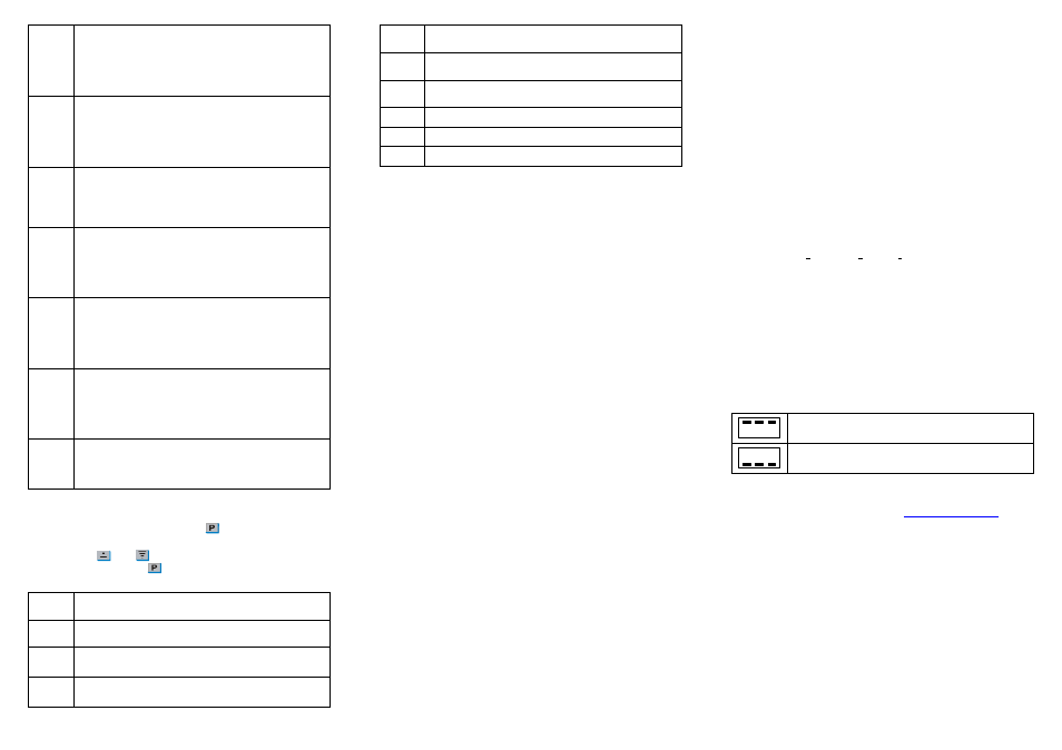
ERROR MESSAGES
Sensor measurement errors force the controller outputs to be turned off. The cause for
these errors may have origin in a bad connection, sensor defect (cable or element) or
system temperature outside the sensor working range. The display signs related to
measurement errors are shown below:
Measured temperature exceeded maximum allowed range for the
sensor. Broken Pt100, Pt1000 or T/C. Short circuited NTC sensor.
Measured temperature is below minimum measurement range of the
sensor. Short circuited Pt100, Pt1000 or T/C. Broken NTC.
WARRANTY
Warranty conditions are available on our web sit