Operation, Configuration protection, Configuration protection usage – NOVUS N320 User Manual
Page 2: Master password, Error messages
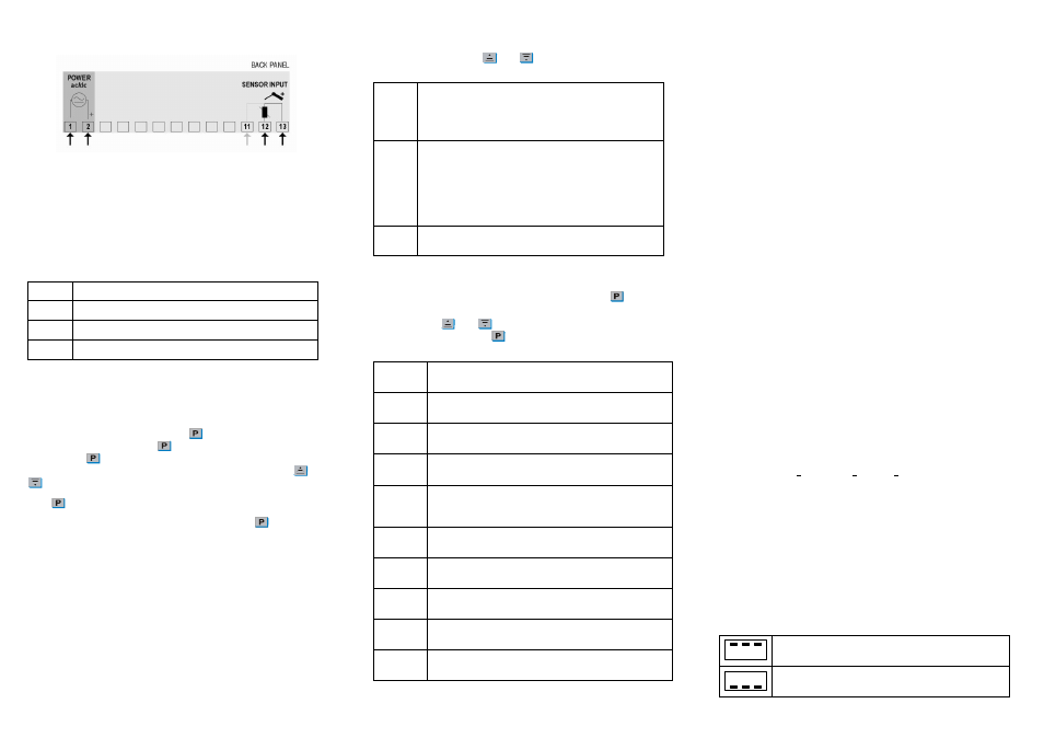
Fig. 1 below shows the temperature meter connections to sensor, mains and
outputs.
Fig. 1 – N320 terminals
Pt100 with 3 conductors. Terminals 11, 12 and 13 must have the same wire
resistance for proper cable length compensation. For 2 wire Pt100, short circuit
terminals 11 and 13.
OPERATION
The temperature meter requires the internal parameters to be configured according
to the intended use for the instrument. The parameters are organized in 3 groups or
levels:
Level
Function
0
Temperature Measurement
1
Configuration
2
Calibration
Upon power-up, the N320 display shows for 1 second its firmware version. This
information is useful when consulting the factory.
After that the thermometer starts to show the temperature measured by sensor.
This is the Temperature Measurement level.
To access level 1 of parameters, press
for 2 seconds until the “uNT”
message is shown. Release the
key to remain in this level. Each new
pressing on the
key will advance to the next parameter in the level. At the end
of the level, the temperature meter returns to the first level (0). Use the
and
keys to alter a parameter value.
Press
again to return to the initial screen (temperature display).
Notes:
1 A parameter configuration is saved when the
key is pressed
to advance to the next parameter in the cycle. The configuration is
stored in a non-volatile memory, retaining its value when the
thermometer is de-energized.
2 If no keyboard activity is detected for over 20 seconds, the
thermometer saves the current parameter value and returns to the
measurement level.
Level 1 – Configuration Level
Contains the configuration parameters to be defined by the user, according to the
system’s requirements. Use
and
keys to set the value. The display
alternates the parameter name and respective value.
Unt
Temperature Unit - Selects display indication for degrees
Celsius or Fahrenheit.
0
- Temperature in degrees Celsius
1
- Temperature in degrees Fahrenheit
typ
Input Type - Selects the input sensor type to be connected to the
temperature meter. Available only for thermocouple models,
allowing selection of types J, K and T.
0
- Thermocouple type J
1
- Thermocouple type K
2
- Thermocouple type T
ofs
Sensor Offset - Offset value to be added to the measured
temperature to compensate sensor error.
Level 2 – Calibration level
The temperature meter is factory calibrated. The following parameters should be
accessed only by experienced personnel. To enter this cycle, the
key must be
kept pressed for 4 seconds.
Don’t press the
and
keys if you are not sure of the calibration
procedures. Just press the
key a few times until the temperature
measurement level is reached again.
pas
Password - Enter the correct password to unlock write
operations for the parameters in the following levels.
[Al
Calibration low - Offset value of the input. It adjusts the lower
measurement range of the sensor.
[Ak
Calibration High - Gain calibration. It adjusts the upper
measurement range of the sensor.
[JL
Cold Junction Offset calibration - This parameter is available
only for thermocouple.
FA(
Factory Calibration - Restores factory calibration
parameters. Change from 0 to 1 to restore the calibration
parameters with factory values.
Prt
Protection - Defines the levels of parameters that will be
password protected. See "Configuration Protection" for details.
Pa(
Password Change - Allows changing the current password to a
new one. Values from 1 to 999 are allowed.
Sn2
Serial number - First part of the temperature meter serial number.
sn1
Serial number - Second part of the temperature meter serial
number.
sn0
Serial number - Third part of the temperature meter serial number.
CONFIGURATION PROTECTION
A protection system to avoid unwanted changes to the temperature meter
parameters is implemented. The level of protection can be selected from partial to
full. The following parameters are part of the protection system:
Pas
When this parameter is presented, the correct password should be entered
to allow changes of parameters in the following levels.
Prt
Defines the level of parameters that will be password protected:
1 - Only calibration level is protected (factory configuration);
2 - Calibration and Configuration levels are protected;
3 - All levels are protected - calibration, Configuration and setpoints.
PA(
Parameter for definition of a new password. Since it is located in the
calibration level, can only be changed by a user that knows the current
password. Valid passwords are in the range 1 to 999.
CONFIGURATION PROTECTION USAGE
PAS
parameter is displayed before entering a protected level. If the correct
password is entered, parameters in all following levels can be changed. If wrong
or no password is entered, parameters in the following levels will be read only.
Important notes:
1- After five consecutive attempts to enter a wrong password, new tentative will be
blocked for the next 10 minutes. If the current valid password is unknown, the
master password can be used only to define a new password for the
temperature meter.
2 - The password for a brand new device is 111.
MASTER PASSWORD
The master password allows user to define a new password for the temperature
meter, even if the current password is unknown. The master password is based in
the serial number of the temperature meter, and calculated as following:
[ 1 ] + [ higher digit of SN2 ] + [ higher digit of SN1 ] + [ higher digit of SN0 ]
for example the master password for the device with serial number 987123465 is:
1 9 3 6
as follows: 1 + sn2= 987; sn1= 123; sn0= 465 = 1 + 9 + 3 + 6
How to use the master password:
1- Enter the master password value at PaS prompt.
2- Go to PA( parameter and enter the new password, which must not be zero (0).
3- Now you can use this new password to access all temperature meter
parameters with modify rights.
ERROR MESSAGES
Sensor measurement errors force the temperature meter outputs to be turned off.
The cause for these errors may have origin in a bad connection, sensor defect
(cable or element) or system temperature outside the sensor working range. The
display signs related to measurement errors are shown below:
Measured temperature exceeded maximum allowed range for
the sensor. Broken Pt1000 or T/C. Short circuited NTC sensor.
Measured temperature is below minimum measurement range of
the sensor. Short circuited Pt1000 or T/C. Broken NTC.