NOVUS N321 User Manual
Page 2
Level 3 – Calibration level
The controller is factory calibrated. The following parameters should be accessed
only by experienced personnel. To enter this cycle, the
key must be kept
pressed for 4 seconds.
Don’t press the
and
keys if you are not sure of the calibration
procedures. Just press the
key a few times until the temperature
measurement level is reached again.
pas
Password - Enter the correct password to unlock write
operations for the parameters in the following levels.
[Al
Calibration low - Offset value of the input. It adjusts the lower
measurement range of the sensor.
[Ak
Calibration High - Gain calibration. It adjusts the upper
measurement range of the sensor.
[JL
Cold Junction Offset calibration - This parameter is available
only for thermocouple.
FA(
Factory
Calibration
-
Restores
factory
calibration
parameters. Change from 0 to 1 to restore the calibration
parameters with factory values.
Prt
Protection - Defines the levels of parameters that will be
password protected. See "Configuration Protection" for details.
Pa(
Password Change - Allows changing the current password to a
new one. Values from 1 to 999 are allowed.
Sn2
Serial number - First part of the controller electronic serial number.
sn1
Serial number - Second part of the controller electronic serial
number.
sn0
Serial number - Third part of the controller electronic serial number.
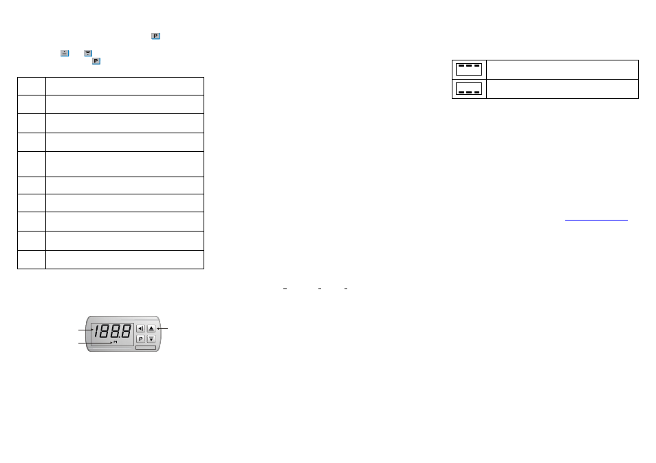
WORKING WITH THE CONTROLLER
The N321 energizes the output relay such as to maintain the process temperature
on the setpoint value defined by the user. The output status led P1 signals when
the control output is on.
DISPLAY
OUTPUT STATUS LED
KEYBOARD
Fig. 2 – Frontal Panel
CONFIGURATION PROTECTION
A protection system to avoid unwanted changes to the controller parameters
is implemented. The level of protection can be selected from partial to full. The
following parameters are part of the protection system:
Pas
When this parameter is presented, the correct password should be entered
to allow changes of parameters in the following levels.
Prt
Defines the level of parameters that will be password protected:
1 - Only calibration level is protected (factory configuration);
2 - Calibration and Configuration levels are protected;
3 - All levels are protected - calibration, Configuration and setpoints.
PA(
Parameter for definition of a new password. Since it is located in the
calibration level, can only be changed by a user that knows the current
password. Valid passwords are in the range 1 to 999.
Configuration protection usage
PAS
parameter is displayed before entering a protected level. If the correct
password is entered, parameters in all following levels can be changed. If wrong
or no password is entered, parameters in the following levels will be read only.
Important notes:
1- After five consecutive attempts to enter a wrong password, new tentative will be
blocked for the next 10 minutes. If the current valid password is unknown, the
master password can be used only to define a new password for the controller.
2 - The password for a brand new device is 111.
MASTER PASSWORD
The master password allows user to define a new password for the controller,
even if the current password is unknown. The master password is based in the
serial number of the controller, and calculated as following:
[ 1 ] + [ higher digit of SN2 ] + [ higher digit of SN1 ] + [ higher digit of SN0 ]
for example the master password for the device with serial number 987123465 is:
1 9 3 6
as follows: 1 + sn2= 987; sn1= 123; sn0= 465 = 1 + 9 + 3 + 6
How to use the master password:
1- Enter the master password value at PaSprompt.
2- Go to PA( parameter and enter the new password, which must not be zero (0).
3- Now you can use this new password to access all controller parameters with
modify rights.
ERROR MESSAGES
Sensor measurement errors force the controller outputs to be turned off. The
cause for these errors may have origin in a bad connection, sensor defect (cable
or element) or system temperature outside the sensor working range. The display
signs related to measurement errors are shown below:
Measured temperature exceeded maximum allowed range for
the sensor. Broken Pt1000 or T/C. Short circuited NTC sensor.
Measured temperature is below minimum measurement range of
the sensor. Short circuited Pt1000 or T/C. Broken NTC.
ELECTRICAL WIRING
It is important to follow the recommendations below:
Signal wires should be installed in grounded conduits and away from power or
contactor wires.
The instrument should have its own power supply wires that should not be
shared with electrical motors, coils, contactors, etc.
Installing RC filters (47 R and 100 nF, series combination) is strongly
recommended at contactor coils or any other inductors.
System failure should always be taken into account when designing a control
panel to avoid irreversible damage to equipment or people.
WARRANTY
Warranty conditions are available on our web sit