Ramp and soak profile program, Link of programs, Event alarm – NOVUS Controller N3000 User Manual
Page 9
NOVUS AUTOMATION
9/11
Table 5 shows the sequence of cycles and parameters presented in the indicator display. There are parameters that must be defined for each alarm
available.
OPERATION CYCLE
AUTO TUNING
CYCLE
PROGRAMMING
CYCLE
ALARM CYCLE
CONFIGURATION
CYCLE
I/O CYCLE
CYCLE
CALIBRATION
PV / SP
Atvn
Tbas
fva1
- fva4
Type
io1
Pass
Avto
Pb
pr n
bla1
- bla4
fltr
Io2
Inl(
PV / MV
Ir
Ptol
kya1
- kya4
Dppo
Io3
Ink(
Pr n
Dt
psp0
– psp7
a1t1
Vnit
Io4
Rsl(
p.seg
(t
pt1
– pt7
a1t2
Offs
Io5
Rsk(
t.seg
Kyst
Pe1
– pe7
a2t1
Spll
Io6
ovl(
rvn
a(t
Lp
a2t2
Spkl
f.fnc
ovk(
Bias
flsk
e.rsp
aven
Rstr
Ovll
Rsp
(j
Ovkl
Rsll
Pas.(
Lbd.t
Rskl
prot
Sfst
IE.ov
Spa1
- spa4
Bavd
Prty
addr
Table 5 - All the controller paramet
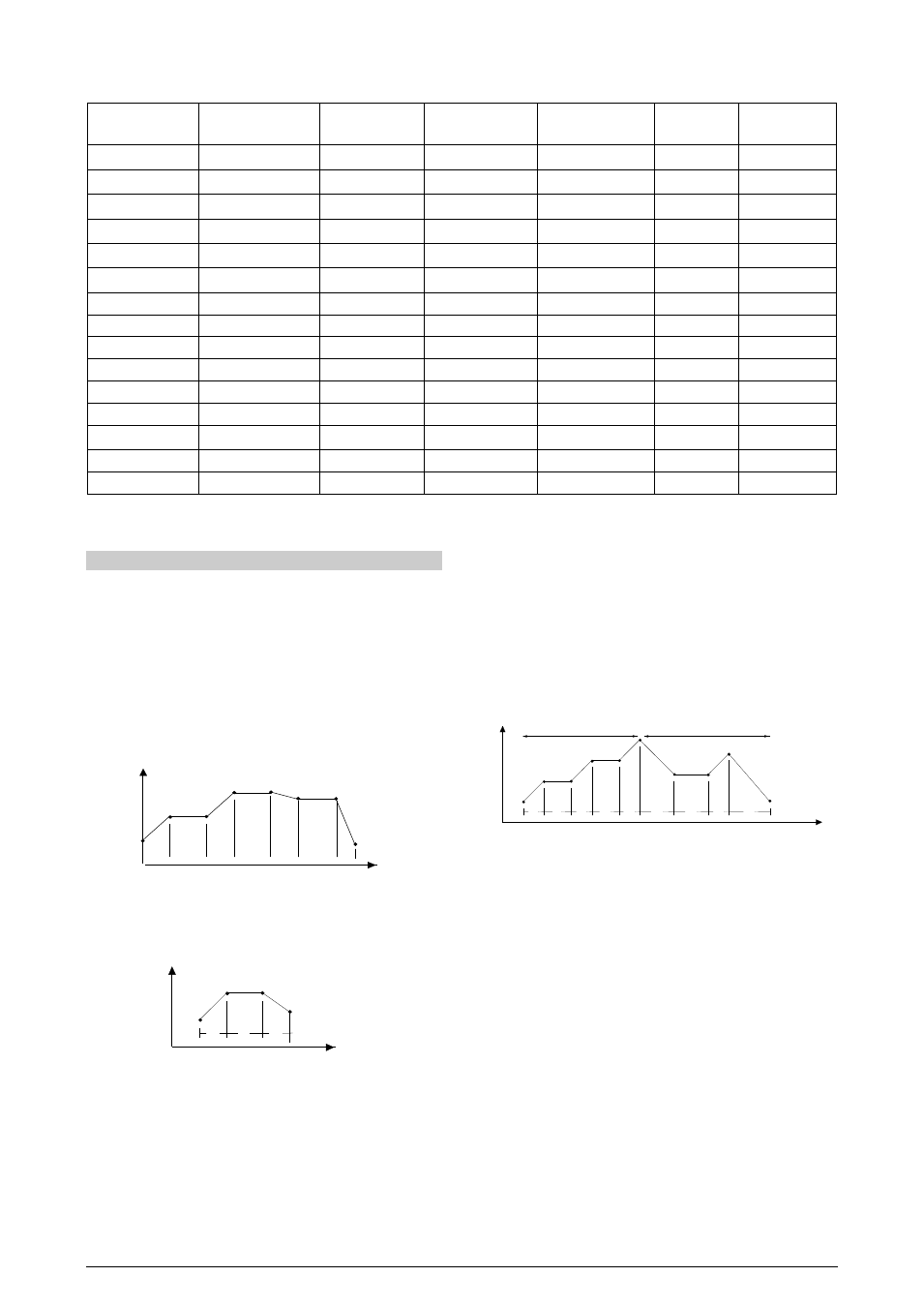
RAMP AND SOAK PROFILE PROGRAM
This feature allows for the elaboration of a behavior profile for the
process. Each program is composed of a set of up to 7 segments,
named RAMP AND SOAK PROGRAM, defined by SP values and
time intervals.
When the program is defined and runs, the controller starts to
automatically generate the SP according to the program.
At the end of the program execution, the controller turns the control
output off (“rvn”= no).
Up to 7 different profiles with 7 segments each can be
programmed.The figure below displays a profile model:
SP
time
T1
T2
T3
T4
T5
SP0
SP1
SP2
SP3
SP4
SP5
SP6
SP7
T6
T7
Fig. 9 - Example of a complete ramp and soak profile
To execute a profile with fewer segments just program 0 (zero) for the
time intervals that follow the last segment to be executed.
SV
time
T1
T2
T3
SP0
SP1
SP2
SP3
T4=0
Fig. 10 - Example of a profile with fewer segments. (T4 is set 0)
The program tolerance “Ptol” defines the maximum deviation
between PV and SV for the execution of the profile. If this deviation is
exceeded, the program will be interrupted until the deviation falls to
within the tolerance band.
Programming 0 (zero) at this prompt disables the tolerance and the
profile execution will not to be halted even if PV does not follow SV
(time priority as opposed to SV priority).
The ramp and soak event function is used to activate alarms at any
segment of program 1. This applies only to program 1.
LINK OF PROGRAMS
It is possible to create a more complex program, with up to 49
segments, joining the seven programs. This way, at the end of a
program execution the controller immediately starts to run another one.
When a program is created, it must be defined in the “LP" screen
whether there will be or not another program.
To make the controller run a given program or many programs
continuously, it is only necessary to link a program to itself or the last
program to the first.
SV
time
T1
T2
T3
T4
T5
T1
T2
T3
T4
SP0
SP1
SP2
SP3
SP4
SP5 / SP0
SP1 SP2
SP3
SP4
Program 1
Program 2
Fig. 11 - Example of two linked programs
EVENT ALARM
To enable this event function the alarms to be activated must be
selected for rS function and are programmed at the PE1 to PE7
prompts. The number to be programmed at the prompt defines the
alarms to be activated.
Note:
1- When recovering from power outage the controller resumes the
ramp and soak execution from the beginning of the interrupted
segment a ramp and soak program:
• Program the tolerance value, SP’s, time and event.
• If any event alarm is required program the ramp and soak event
function.
• Set the control mode to automatic.
• Habilitar a execução de programa na tela “rS “.
• Start control at the rvn prompt by selecting YES.
Before executing the program the controller waits for PV to reach the
first set point SP0. Should any power failure occur the controller
resumes at the beginning of the segment it currently is.