Nor-Lake Capsule Pak Refrigeration Systems User Manual
Page 7
07/14 Rev. H 040086
7
Freezer Models 100 and 150 or Cooler Model 075
1. After uncrating, before attempting to attach the refrigeration system to the walk-in, a substantial temporary
support should be built. The support should be approximately 28 inches high and placed directly below the wall
opening of the walk-in.
Note: Due to the weight of these systems it is highly recommended that proper lifting equipment, such as a fork
truck, be utilized during installation.
2. Lift the refrigeration system onto the temporary support. Determine whether the coil section sleeve is positioned
properly so that it can be inserted into the opening without being bent or damaged. Shim the system appropriately
so that this can be accomplished.
3. Carefully slide the entire system so that the coil section sleeve enters the opening without disturbing the
temporary support below the refrigeration system. Continue until the gasket around the coil section contacts and
seals around the entire perimeter of the coil section. Shim the system and adjust it accordingly so that the gasket
seal will be uniform on all four sides.
4. Using the section-latching wrench provided for the erection of the walk-in, insert the wrench into the latch access
holes of the coil section. Turn each of the locks clockwise until the latches engage the strikes in the walk-in. Turn
the lock until a full stop is encountered. DO NOT REMOVE THE TEMPORARY SUPPORT!
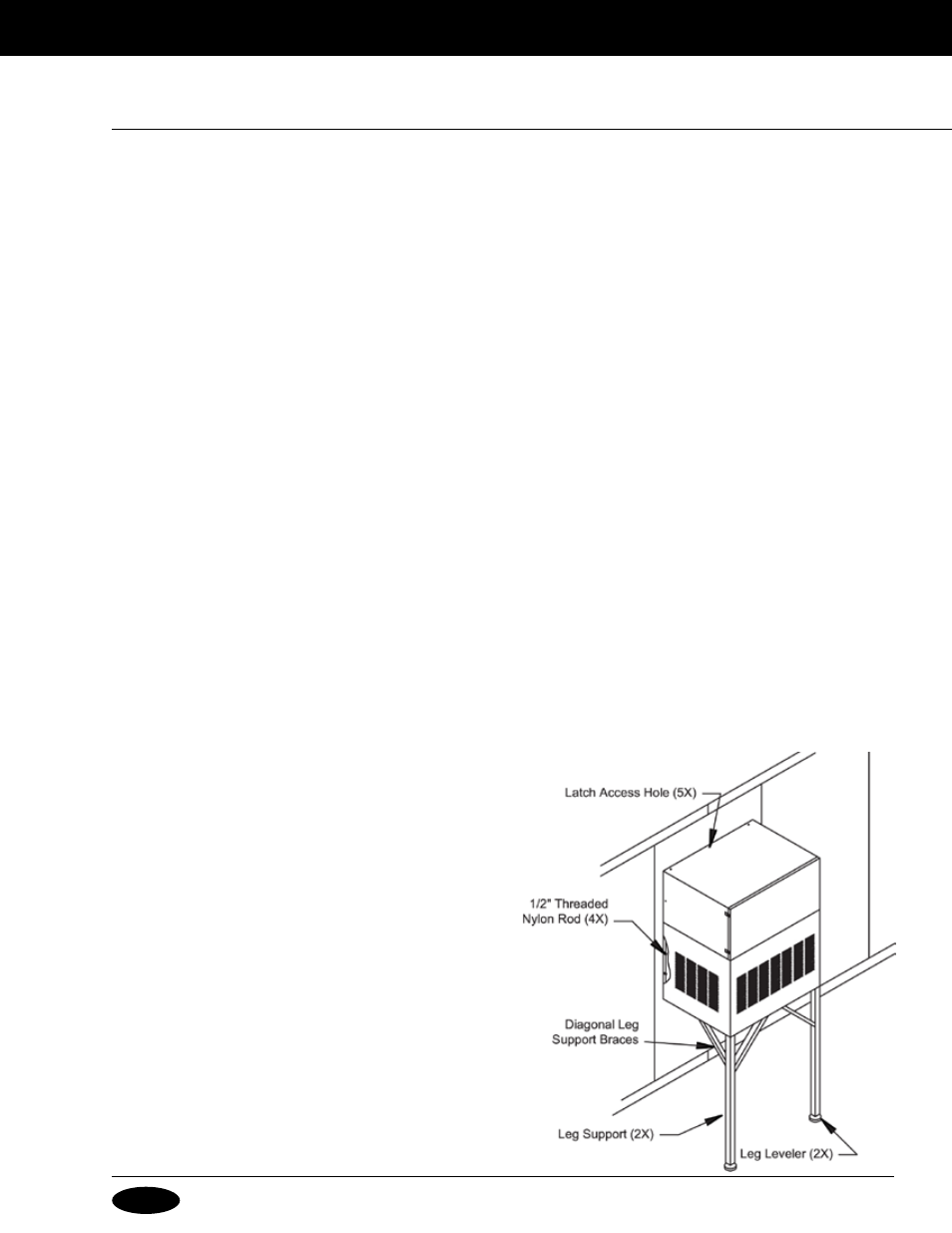
5. Remove the louver assembly and drill four 9/16” diameter holes through the two upright angles of the condensing
unit section. Drill completely through the walk-in wall and insert the 1/2" threaded nylon rods. Secure with the flat
washers and nuts provided. Refer to Figure 2.
6. With the leveling screws threaded completely into the leg support, insert the leg support into the leg retainers
at the outer corners of the condensing unit section. Unscrew the leg leveling screws until they contact the floor or
other supporting surface. Note: If the supporting surface is extremely uneven, suitable shimming material must be
provided under one or both of the leg supports.
7. Attach the diagonal leg support braces using the
threaded fasteners provided. Make the final adjustments
to the leg leveling screws so that they serve as supporting
devices to the outer edge of the refrigeration system.
8. Insert plug buttons into each of the latch access holes.
9. Remove the temporary support assembly that was
provided in Step 1.
g
eneRal
i
nStallation
i
nStRuCtionS