Warning – Alliance Laundry Systems D677I User Manual
Page 28
© Copyright, Alliance Laundry Systems LLC – DO NOT COPY or TRANSMIT
Installation
512680
26
Step 8: Recheck Steps 1-7
Refer to Installer Checklist on the back cover of this
manual and make sure that dryer is installed correctly.
Step 9: Check Heat Source
Electric Dryers
Close the loading door and start the dryer in a heat
setting (refer to the Operation section). After the dryer
has operated for three minutes, the exhaust air or
exhaust pipe should be warm.
Gas Dryers
IMPORTANT: This operation is to be conducted
by qualified personnel only.
To view the burner flame, remove the lower front
panel of the dryer.
Close the loading door, start the dryer in a heat setting
(refer to the Operation section). The dryer will start,
the igniter will glow red and the main burner will
ignite.
IMPORTANT: If all air is not purged out of gas
line, gas igniter may go off before gas is ignited. If
this happens, after approximately two minutes
igniter will again attempt gas ignition.
IMPORTANT: If igniter does not light, make sure
gas is turned on.
After the dryer has operated for approximately five
minutes, observe burner flame through lower front
panel. Adjust the air shutter to obtain a soft, uniform
blue flame. (A lazy, yellow-tipped flame indicates lack
of air. A harsh, roaring, very blue flame indicates too
much air.) Adjust the air shutter as follows:
1. Loosen the air shutter lockscrew.
2. Turn the air shutter to the left to get a luminous
yellow-tipped flame, then turn it back slowly to
the right to obtain a steady, soft blue flame.
3. After the air shutter is adjusted for proper flame,
tighten the air shutter lockscrew securely.
4. Reinstall the lower front panel.
After the dryer has operated for approximately three
minutes, exhaust air or exhaust pipe should be warm.
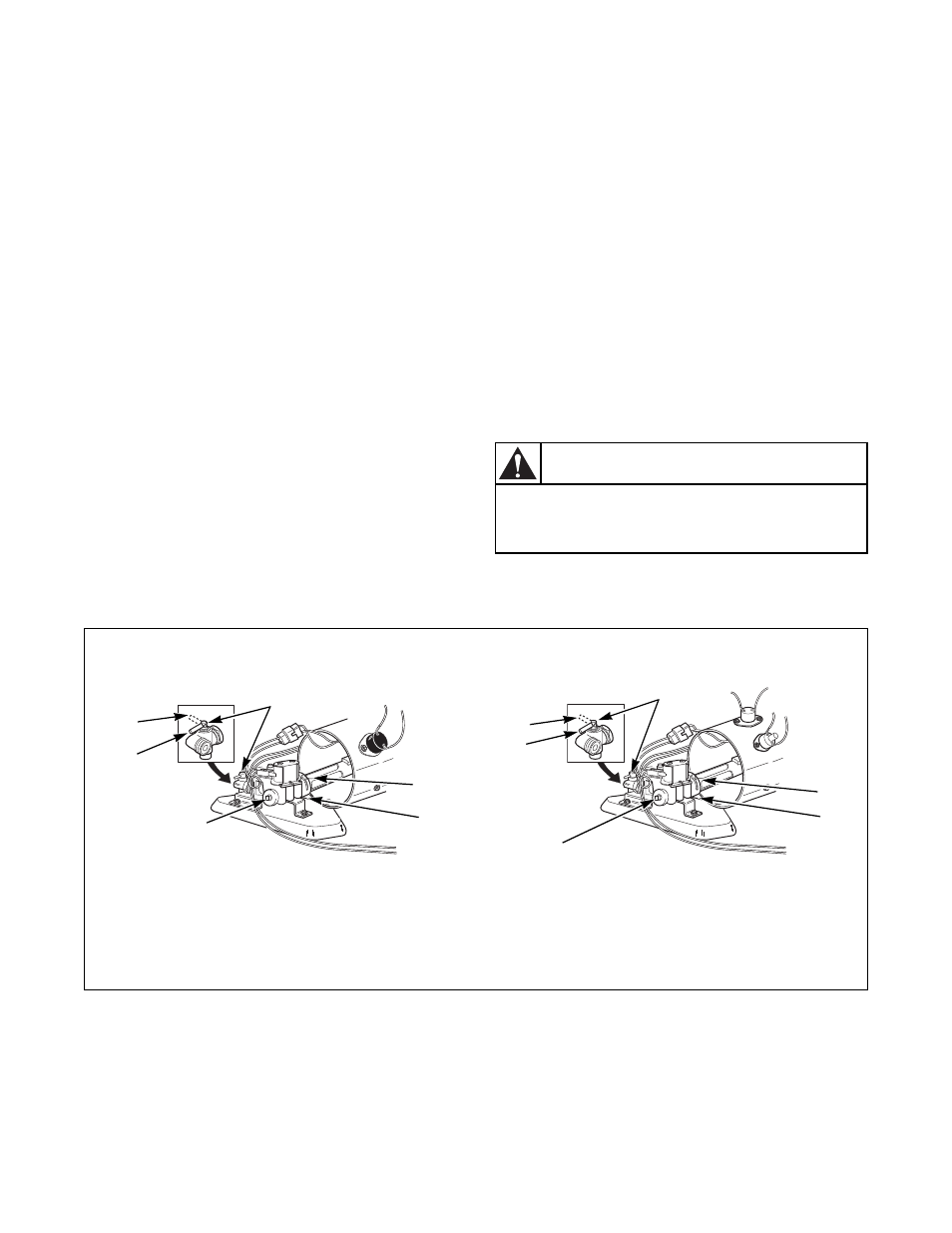
Figure 33
For personal safety, lower front panel must
be in place during normal operation.
W046
WARNING
D700I
DRY2235N
1
Closed Position
5
1/8 in. (3.1 mm) Pipe Plug
2
Shut-Off Valve Handle
(For checking manifold pressure)
3
Air Shutter Lockscrew
6
Open Position
4
Air Shutter
D700I
1
4
3
6
2
5
COIN SLIDE, MDC, AND NETMASTER MODELS THROUGH
SERIAL NO. 0803 AND NONMETERED MODELS
1
4
3
6
2
5
COIN SLIDE, MDC, AND NETMASTER MODELS
STARTING SERIAL NO. 0804