Alliance Laundry Systems D677I User Manual
Page 24
© Copyright, Alliance Laundry Systems LLC – DO NOT COPY or TRANSMIT
Installation
512680
22
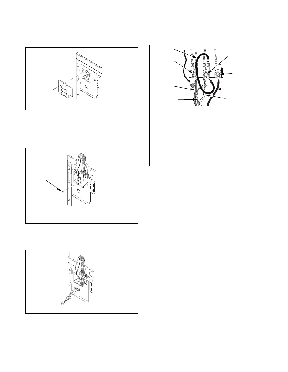
1. Disconnect power to dryer.
2. Remove access cover from rear of dryer.
Figure 17
3. Remove ground screw from ground to neutral
wire and save for use in Step 5. Ground to neutral
wire will be attached to the neutral terminal in
Step 6.
Figure 18
4. Use a strain relief and insert end of power cord
through power supply hole.
Figure 19
5. Attach power cord ground (green) wire to rear
bulkhead using ground screw removed in Step 3.
Figure 20
6. Use the three screws from the accessories bag to
attach the remaining power cord wires to the
terminal block as follows:
a. Red wire to “L1” terminal.
b. Black wire to “L2” terminal.
c. White wire to neutral terminal.
IMPORTANT: When installing the white wire, loop
the free eyelet end of the ground to neutral wire
(removed in Step 3) and attach along with the white
wire to the neutral (center) terminal on the
terminal block.
7. Tighten all screws firmly.
IMPORTANT: Failure to tighten these screws
firmly may result in wire failure at the terminal
block.
8. Secure the strain relief to the power cord, or
wires, where they enter the dryer cabinet.
9. Check the continuity of the ground connection
before plugging the cord into an outlet. Use an
acceptable indicating device connected to the
center grounding pin of the plug and the green
screw on the back of the control hood.
10. Reinstall access cover and screw.
DRY2467N
DRY2468N
1
Ground Screw
DRY2469N
1
DRY2482N
1
Neutral Terminal
2
“L2” Terminal
3
Black
4
White
5
Ground
6
Red
7
“L1” Terminal
8
Ground to Neutral Wire
6
2
1
3
5
7
4
8