American Dynamics ADCTDN0230P User Manual
Page 25
25
1.
Remove the camera-mounting bracket locking screws (x2).
The camera-mounting bracket is removed from the camera.
2.
Mounting the camera-mounting bracket on top of the camera
3.
Mounting the camera onto a mount, pan/tilt unit and the like
Note:
● Use a camera-mounting screw with a length between 5mm and 7mm from
the camera-mounting face. Do not use a screw that is longer than the
specified length. It may damage the internal parts.
● To mount the camera-mounting bracket on top of the camera, use the
screw holes on the back panel.
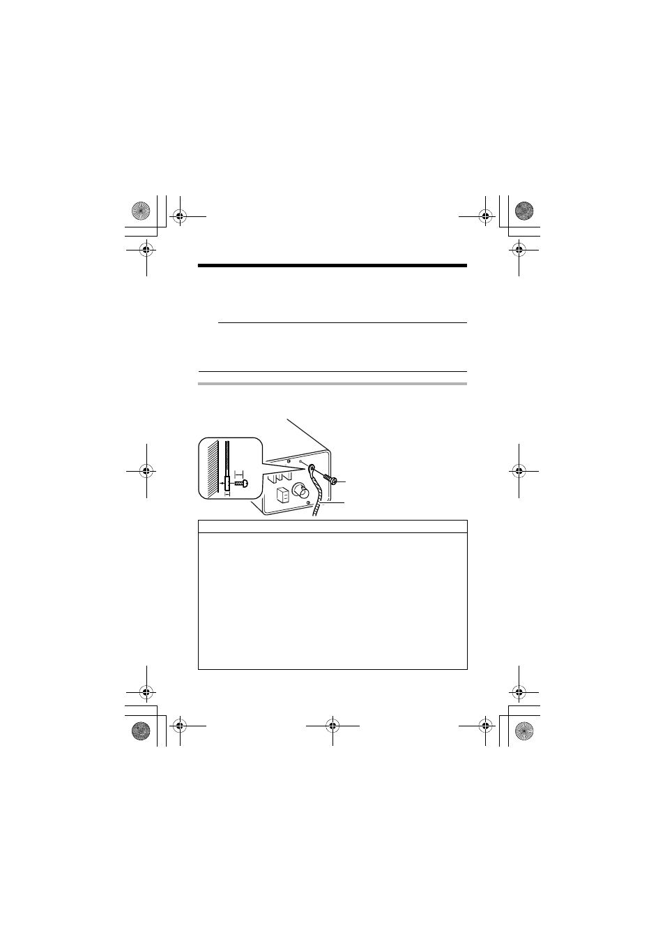
Fall Prevention
Use the black mounting screw on the back of the camera to install the fall
prevention wire
VIDEO
O
UT
2mm
6mm
M3 x 6mm
Fall Prevention Wire
Precautions regarding fall prevention
● Special attention is required when installing the camera to the wall or
ceiling. You should not engage in the installation work yourself. Ask a
professional to do the job, since a falling camera can result in injuries
and accidents.
● When installing the camera on a mount, pan/tilt unit and the like, make
sure to install it firmly using a rotation-preventive hole to prevent fall.
● To prevent fall, connect the camera to a section with sufficient strength
(ceiling slab or channel) using a fall prevention wire.
● Pay attention to the length, strength, routing and material (insulation
properties) of the fall prevention wire used.
● Use the black screw (M3 x 6 mm) on the back of the camera for the
installation of the fall prevention wire. Using other screws of different
sizes may damage the inside.
● Before use make the fall prevention wire as short as possible.
● Use a fall prevention wire of sufficient strength and terminal treatment to
support the weight of the camera, lens and fixer.
ADCTDN2412N_P_EN.book Page 25 Friday, September 28, 2007 12:49 PM