2 wiring, Wiring, Iclass – HID multiCLASS RP Series Hi-O Installation Guide User Manual
Page 4: 配線 布线 배선, Таблица расключения проводов
iCLASS
R10, R15, R30, R40, and RK40
INSTALLATION GUIDE
4
©2009 HID Global Corporation. All rights reserved.
3170-901 B.0
CP1 CP2
P6
CP1
CP2
P6
2
1
3 4
6
5
7
2 1
3
4
6 5
7
Terminal
Block Wiring
CP1
CP2
HS
I_
SA
BO
TG
_I
N
HS
I_
O
C_
O
UT
TA
MPER/O
C_O
UT
D1
D0
CA
N_
L
CA
N_
H
BE
EP
G
RN
L
ED
G
ND
VS
PL
Y
G
ND
RE
D LE
D
HOLD
ATTENTION
Observe precautions for handling
ELECTROSTATIC SENSITIVE DEVICES
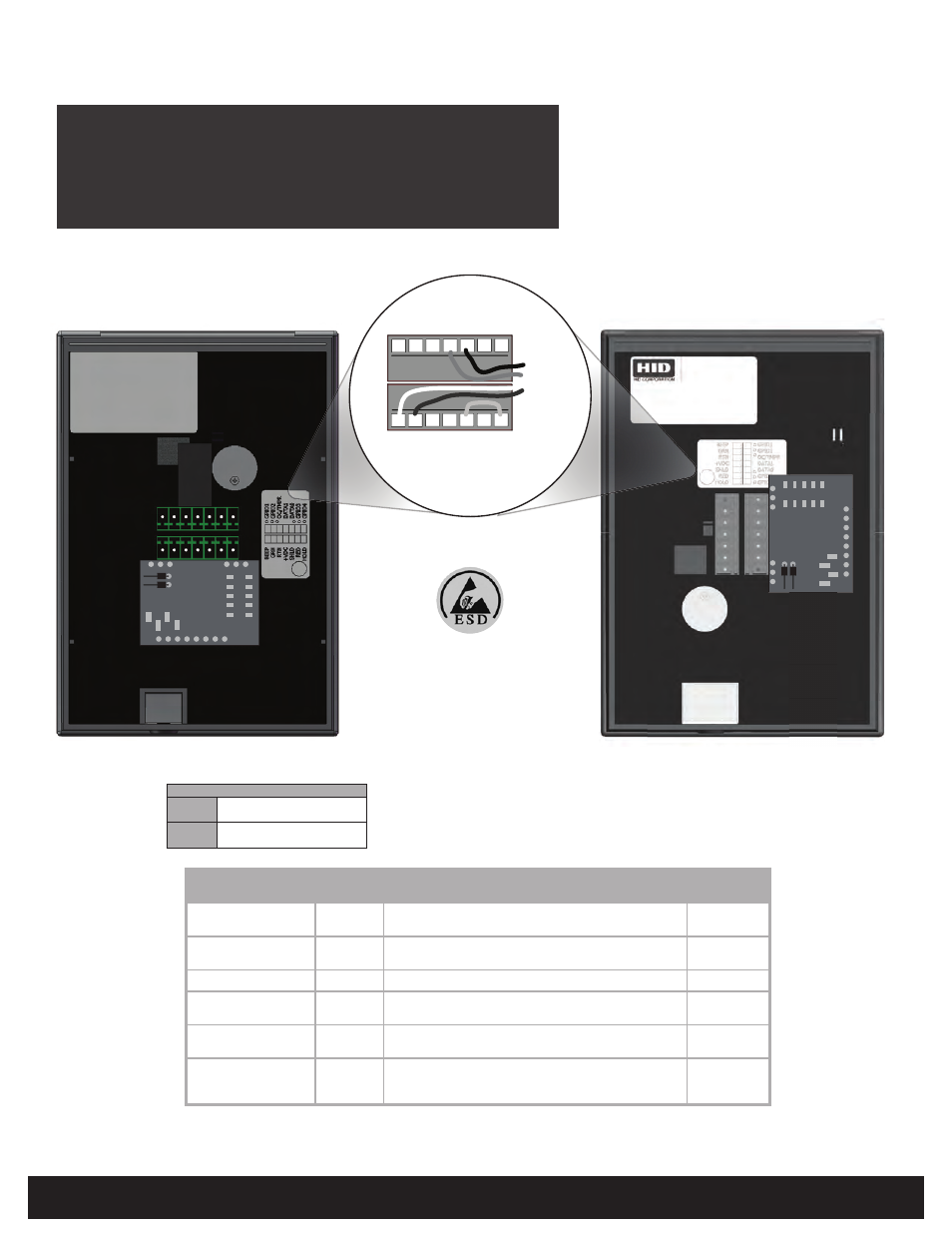
Wiring
C
ableado
C
âblage
f
iação
V
erdrahtung
C
ablaggio
配線
布线
배선
2
ТАБЛИЦА рАсКЛЮЧЕнИЯ ПрОВОДОВ
P6 Group Select Option
Group 1
(Default)
Shorted
(Outside - Jumper Installed)
Group 2 Open
(Inside - No Jumper)
Note
: P6 connector found on the underside of module.
PIN
COLOR
DESCRIPTION
PCB
LOCATION
GND
Black
Ground (RTN) - External supply common return. Also a con-
nection point for CAN_GND and optional CAN_SHIELD.
CP1-3
CP1-5
+VSPLY
Red
+VDC (5-16 VDC) External power supply input.
WARNING: Do not connect Hi-O 24 VDC Power Supply.
CP1-4
CAN_H
White
Differential CAN bus 'high' signal I/O pin
CP2-1
CAN_L
Brown
(Alt Green) Differential CAN bus 'low' signal I/O pin
CP2-2
Core OC_OUT /
SABOTAGE_OUT
OC and Tamper switch output from core module (open col-
lector). Requires a jumper to HSI_SABOTAGE_IN
CP2-5
HSI_SABOTAGE_IN
Tamper switch detects input to HSI module. Pulled up to
+5VDC. Allows sabotage detection and messaging over
Hi-O network. Requires a jumper to OC_OUT.
CP2-7
Terminal Reader with Hi-O Module
CAUTION: Tamper functionality is dependent upon correctly installing
the jumper wire between CP2-5 and CP2-7. Ensure correct installation
and test the tamper switch after installation.
Keypad Terminal Reader
with Hi-O Module