Electrical connections, Option switches, Track selection – HID Magnetic Stripe Reader 740 Installation Guide User Manual
Page 2: Installation instructions, Powering on and self-test, Diagnostic tests
Electrical Connections
Connections from the reader cable to the host cable should be
crimped or made with twist-on wire nuts. Unplug the reader
connector before making the following splices
NOTE: The two blue wires connect to the HEATER BAR which
must be powered by a 24VAC or 24ADC source (3110-7402
Reader only).
Control and data lines are normally High (+5V) when idle and
pulled to common when active (less than 1V).
Two 22GA White wires convey the status of a tamper switch
that indicates whether the reader is properly mounted or
detached. The switch is CLOSED when the reader is mounted
and OPEN when it is detached.
Option switches
To set the reader options, you must know:
1 Are the cards coded with EMPI or ANSI data?
2. Are the cards coded on track I or track II?
3. Does the host system expect Wiegand 26-bit, Wiegand
34-bit or clock-and-data format?
3110-7401 Options
A
B
C
off
on off EMPI
Wiegand
26-bit
off
on on EMPI
Wiegand
34-bit
on
off off ANSI clock-and-data all bits
on
off on ANSI all bits Wiegand
on
on off ANSI Wiegand 26-bit
on
on on ANSI Wiegand 34-bit
“D” IS NOT USED-SET TO OFF
These selections cover the most common uses. If they do not
serve your application, consult your system supplier for their
setup method.
Track Selection
Readers are shipped reading the track II physical location. If
your card is coded on track 1, disassemble the read head
assembly and rotate the reading head 180 degrees.
Installation Instructions
CAUTION
Before touching any internal reader parts, touch a grounded
surface to discharge static electricity from your body.
1.
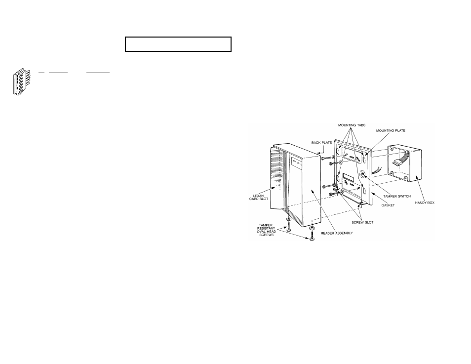
If not mounting to an electrical handy-box, select a suitable
flat surface and use the mounting plate both as a template
to establish drill hole location and as a guide to remove
sufficient material to allow clearance for connection of the
pig-tail to the wiring cable, and the tamper switch. The
tamper switch can be found in the hardware package. If
desired, it can be installed either as shown, or to the back
plate with the tamper switch plunger facing the mounting
plate. A hole in the back plate is provided for this purpose.
2. Pull the required cable between host controller and reader
mounting location. Connect the wire cable to the host.
3. To install, you must first disassemble the reader assembly
from the mounting plate. Use the special oval head screw
driver (AVSAFE driver obtained separately) to loosen the
(2) tamper resistant oval head screws from the bottom of
the reader.
NOTE: It is not necessary to fully remove screws. Just loosen
enough to remove the mounting plate. This will simplify re-
assembly.
4. Attach the provided pig-tail connector to the wire cable at
the mounting location. Connections can be crimped or
made with twist-on wire nuts. Follow the appropriate color
code and wire lead function.
5. Pass the connector through the cut-out in the mounting
plate, and mount the plate to the mounting surface using
the appropriate mounting holes in the plate. The type of
mounting bolts (not provided) will be determined locally by
the installer. They must provide a strong secure mounting.
6. Make sure the wire nuts, or crimped connectors are
located in the wall cavity, and only the pig-tail connector
passes through the mounting plate.
7. Plug the connector into the back of the reader circuit
board. The connector is designed to fit only one way.
Carefully align the pin terminals of the circuit board with
the corresponding holes in the connector and gently push
together with a slight rocking motion.
If not already accomplished, set the appropriate
option switches on the back of the reader circuit
board.
8. Attaching the reader assembly to the mounting plate is the
reverse of disassembly. Carefully align the (4) mounting
tabs on the mounting plate with their corresponding slots in
the back plate. Make sure the (2) oval head screws until
the reader assembly is pulled firmly against the mounting
surface. Do not over tighten these screws.
NOTE: This operation also depresses the tamper switch
plunger.
9
.
Test the reader as appropriate.
Powering On and Self-test
Upon first application of power, the reader does a self-test
sequence. Observe that the reader's Green LED flashes four
times.
If the reader does not make the above confirmation or
continues with short double flashes, the self-test has failed and
the reader must be replaced.
Diagnostic Tests
If the reader completes the self-test by flashing the LED but will
not read cards the following steps apply:
1.
Check that the voltage at the red and black wires is
between 8.0 and 13.0 VDC.
2.
Verify wiring to the host controller.
3.
Test reader by exchanging with another unit.
1
2
3
4
5
6
PIN FUNCTION
WIRE COLOR
1
+12 VDC
RED
2
LED Control Line A
BROWN
3
Data "1" /Data
WHITE
4
Data "0" /Clock
GREEN
5
COMMON
BLACK
6
LED Control Line B
YELLOW
HEATER
BAR BLUE
4.
Do not attempt to adjust the reading head or its mount. It
is factory calibrated and not field serviceable.
Internal damage or electronic failure requires replacement
of the complete reader.