Installation instructions, Keypad data, Specifications – HID Magnetic Stripe / Prox Reader 230 and 240 Installation Guide User Manual
Page 2: Regulatory, Diagnostic tests
Installation Instructions
WARNING: To prevent damage to equipment,
make all connections with power off.
1. If the reader is to be mounted on a mullion or firm flat
surface, pull an appropriate length and gauge of cable
between the host and mullion.
2. If the reader is to be mounted on a flat surface rather
than a handy box, use the reader base both as a
template to establish drill locations for suitable molly
fasteners, etc. (not provided), and as a guide to remove
sufficient material for wire clearance. Then pull the
appropriate wire between the host and reader location.
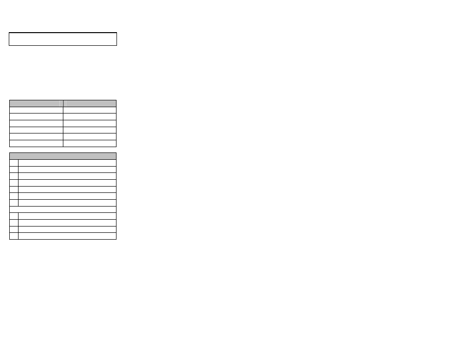
3. Connect the wires of the pigtail assembly to the cable
end at the reader location. Connections can be crimped
or made with twist on wire nuts.
FUNCTION WIRE
COLOR
+5 to 24 VDC
RED
Green LED
BROWN
Data "1" /Data Output
WHITE
Data "0" /Clock Output
GREEN
COMMON
BLACK
Buzzer
YELLOW
Format Selection Switch (16 position rotary)
1
ABA mag stripe to All Bits Wiegand & HID prox*
2
ABA mag stripe to Wiegand 26 bit & HID prox*
3
ABA mag stripe to Wiegand 34 bit & HID prox
4
EMPI mag stripe & EMPI prox to Wiegand 26 bit
5
EMPI mag stripe & EMPI prox to Wiegand 34 bit
6
EMPI mag stripe to Wiegand 26 bit & HID prox*
7
EMPI mag stripe to Wiegand 34 bit & HID prox*
Following ABA only ANSI 10 or 12 (5/5 or 6/6)
8
ABA mag stripe & Proxi 10 prox to Wiegand 26 bit
9
ABA mag stripe & Proxi 10 prox to Wiegand 34 bit
A
ABA mag stripe to Wiegand 26 bit & HID prox
B
ABA mag stripe to Wiegand 34 bit & HID prox
* HID Prox data output is determined by card encoding, up to 36
bits max. This reader will not read HID 37 bit or formats which
require additional processing by the reader.
4. Connect the other end of the cable to the host controller
being sure to follow the appropriate color code and wire
lead functions.
5. Verify that the cards to be read are encoded with the
selected data format.
6. Observe the reader LED; it should flash green four times
as a self-test when first powered on. If this is not the
case, or it continues with short double flashes, a problem
exists, refer to the Diagnostic Tests section.
Keypad Data
The model 240 keypad sends data keystroke-by-keystroke to
the host controller in an 8-bit (per keystroke) data format.
Diagnostic Tests
The Model 230 and 240 Proximity Card Readers are factory
calibrated and are not field serviceable.
1. A card with the expected card format will cause the
reader LED to "wink" dark and the buzzer to sound for
0.1 second while outputting data to the host.
2. Direct substitution with a known good reader is the best
way to isolate the problem.
3. If the reader is exchanged and the problem still exists,
measure the voltage drop at the reader between the RED
(Positive) and the BLACK (Common) wire with the reader
connected to the host. It should measure between 5 and
24.0 VDC. Low voltage is a common source of problems.
4. Verify that the card used to test is a known good card,
and is authorized in host memory. Verify the reader
options are set correctly for that particular host, and the
proper "Comparison Number" or site code has been
recorded in host memory.
5. Verify the wiring, continuity, and connections between
reader and host. If possible, switch the reader input
wiring at the host to another known good input terminal
group.
6. If the problem still cannot be resolved, contact your HID
reseller for assistance.
Specifications
INPUT:
Magnetic Stripe: ABA/ANSI/ISO & EMPI Proximity:
HID 26 – 36 bit or EMPI or PROXI 10.
(Will not read HID
37 bit or formats which require additional
processing by the
reader.)
READING DISTANCE:
7” (17.7 cm) typical at 12 VDC (6” or 15.2 cm if
mounted on metal)
6” (15.2 cm) typical at 5 VDC (5” or 12.7 cm if mounted
on metal)
DATA OUTPUT:
Proximity Data: Output based on card type. HID up to
36 bit.
Magnetic Stripe Data: Wiegand 26, Wiegand 34 or All
its Wiegand (up to 64 bits)
LED CONTROL:
Red/Green control with brown wire control line (ground
wire)
WIRE LENGTH:
200 feet (61m) with #22 AWG wire
500 feet (153m) with #18 AWG wire
TEMPERATURE RANGE:
-35 to +66 degrees Celsius (-31 to 150 degrees
Fahrenheit).
POWER:
5 VDC to 24.0 VDC input
120 mA nominal at +5.0 VDC
170 mA nominal at +12.0 VDC
READ SPEED:
80 milliseconds
DIMENSIONS:
4.70 in H x 3.00 in W x 1.54 in D
11.9 cm H x 7.6 cm W x 3.9 cm D
BUZZER:
Activates momentarily upon card acceptance and
Keystroke activation or grounding of yellow wire.
Regulatory
FCC
This device complies with part 15 of the FCC rules.
Operation is subject to the following two conditions: (1) this
device may not cause harmful interference, and (2) this
device must accept any interference received, including
interference that may cause undesired operation.
Changes or modifications not expressly approved by the
party responsible for compliance could void the user’s
authority to operate the equipment.
UL
This Proximity Reader is intended to be powered from a limited
power source output of a previously certified power supply.
This Reader is intended to be used with UL 294 Listed Control
Equipment.
CE Marking
HID Global hereby declares that this proximity reader is in
compliance with the essential requirements and other relevant
provisions of Directive 1999/5/EC.