Specifications, Wiring, Internal optical tamper – HID EDGE EVO Hi-O Interface Door Module Installation Guide User Manual
Page 2: Relay jumpers, Door module
Door Module
EDM-M
82342-901 B.1
INSTALLATION GUIDE
2
©2009 - 2011 HID Global Corporation. All rights reserved.
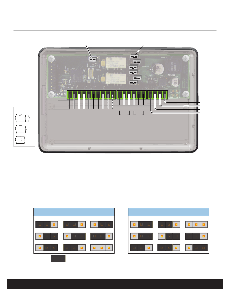
Wiring
10
P3
1
4
P1 1
Hi-O Group Select Jumper
Short = Group 1, Open = Group 2
Outside Door
Inside Door
( )
CAN V+
GND
CAN H
CAN L
Relay Jumpers
6
P10
1
P9
P5
P8
P6
P4
P7
HI-O CANbus
Door
Mon
REX
*
-
+
BATT
AC
-
+
-
+
-
+
DS
NC
CO
M
NO
AUX
SENSE
* Internal Optical Tamper Disable Jumper
NC
CO
M
NO
Note: Connect the Door Monitor to avoid a Force Door Alarm.
Internal Optical Tamper
To disable the internal optical tamper sensor for the right side PCB (reader interface board), attach a jumper wire from P3 pin 1
to P3 pin 2.
Note: If desiring an external tamper, wire an unsupervised Normally Closed contact and replace the jumper.
Relay Jumpers
AUX Wet
CAN V+
AUX Wet
+12VDC
AUX Dry
DS Wet
CAN V+
DS Wet
+12VDC
DS Dry
3
1
P9
P5
P8
3
1
3
1
3
1
P6
P4
P7
3
1
3
1
JUMPER =
Optional
Supervised Inputs
1-6K
N/O
1-6K
N/C
1-6K
1-6K
N/O
- bioCLASS Installation Guide (12 pages)
- Crescendo Integration (54 pages)
- EDGE EVO EDM-M Door Module Installation Guide (4 pages)
- EDGE EVO EDWM-M Door-Wiegand Module Installation Guide (4 pages)
- EDGE EVO EH400 Hi-O Controller Installation Guide (12 pages)
- EDGE EVO Solo ESH400 Hi-O Controller Installation Guide (12 pages)
- EDGE EVO EH400-K Standard Controller Installation Guide (12 pages)
- EDGE EVO Solo ESHR40 Hi-O Controller/Reader Installation Guide (12 pages)
- EDGE EVO EIM-M Hi-O Input Module Installation Guide (2 pages)
- EDGE EVO EIM-M Input Module Installation Guide (2 pages)
- EDGE EVO ELM Hi-O Lock Module Installation Guide (2 pages)
- EDGE EVO ELM Lock Module Installation Guide (2 pages)
- EDGE EVO EVM Hi-O Voltage Module Installation Guide (2 pages)
- EDGE EVO EVM Voltage Module Installation Guide (2 pages)
- EDGE EVO Solo ESH400-K Networked Controller Installation Guide (10 pages)
- EDGE EWM-M Hi-O Wiegand module Installation Guide (4 pages)
- EDGE Plus Installation Guide (2 pages)
- EntryProx Installation Guide (58 pages)
- MIFARE Reader Installation Guide (6 pages)
- Hi-O iCLASS Installation Guide (49 pages)
- iCLASS Keypad Installation Guide (12 pages)
- iCLASS R Installation Guide (12 pages)
- iCLASS RK Series Rev C Installation Guide (12 pages)
- iCLASS SE Installation Guide (10 pages)
- iCLASS SE/ multiClass SE Installation Guide (10 pages)
- Magnetic Stripe / Prox Reader 230 and 240 Installation Guide (2 pages)
- Magnetic Stripe Reader 644 Installation Guide (2 pages)
- Magnetic Stripe Reader 740 Installation Guide (2 pages)
- Magnetic Stripe Reader 780 Installation Guide (2 pages)
- MaxiProx Installation Guide (19 pages)
- multiCLASS / Magnetic Stripe Installation Guide (12 pages)
- multiCLASS / Magnetic Stripe with Keypad Installation Guide (10 pages)
- multiCLASS RP Series Hi-O Installation Guide (6 pages)
- pivClass Installation Guide (8 pages)
- Prox Programmer Installation Guide (21 pages)
- ProxPass Installation Guide (3 pages)
- ProxPoint Installation Guide (3 pages)
- ProxPoint Plus Installation Guide (2 pages)
- ProxPro II Installation Guide (2 pages)
- ProxPro Installation Guide (14 pages)
- Serial ProxPro Reader Installation Guide (10 pages)
- SmartID Mounting Plate Installation Guide (2 pages)
- SmartID Spacer Installation Guide (2 pages)
- VertX EVO V1000 Installation Guide (19 pages)