Virtual lan configuration, Menus, Figure 35 virtual lans menu – Allied Telesis AT-S21 User Manual
Page 49: Figure 36 vlan example, Virtual lan configuration -17, 9luwxdo#/$1#&rqiljxudwlrq
$70654#8VHU·V#*XLGH
3-17
9LUWXDO#/$1#&RQILJXUDWLRQ
Menus:
Virtual LANs
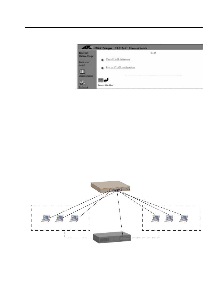
Figure 3-5 Virtual LANs Menu
This switch supports port based VLANs only.
By default, the switch has one VLAN (all ports’ VLAN assignment
showing as Default VLAN) and one spanning tree. In most
situations, users find the defaults acceptable and do not require
further configuration; however, your network may require assigning
end stations into logical groupings, regardless of their physical
location. You can group your end stations logically through VLANs.
Information exchange is confined within the members of a given
VLAN. A VLAN constitutes one broadcast domain; therefore,
broadcast packets from an end station only go to other stations
within the same VLAN.
VLANs cannot communicate with each other through the switch;
they require a router to do this (Figure 3-6).
Figure 3-6 VLAN Example
RS-232
TERMINAL P
ORT
STATUS
10BASE-T / 100
BASE-TX
FAST ETHERNET SWITCH
PORT ACTIVIT
Y
10BASE-T / 10
0BASE-TX
Router
VLAN 1
VLAN 2
AT-8124XL