How the switch reports problems, How the switch reports problems -4 – Allied Telesis AT-8126XL User Manual
Page 38
Troubleshooting
3-4
How the Switch Reports Problems
The switch detects and processes errors as follows:
" The LEDs indicate problems with the port and power.
Table 3-1 describes the switch LEDs.
" In a TCP/IP environment, if you have configured the software
correctly, the management software triggers an SNMP trap
message. As a result, the software then sends traps to alert the
network manager when a trigger occurs. This type of software
configuration allows the network administrator to pro-
actively monitor their network.
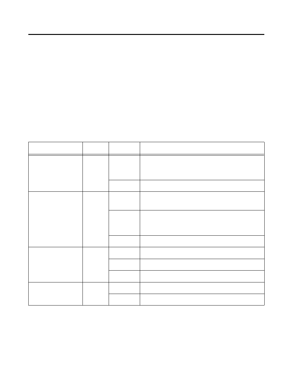
Table 3-1 lists and describes the switch LEDs.
Table 3-1 Switch LEDs
LED
Color
State
Description
Power (system)
Green
On
The switch is receiving power, voltage is within
the acceptable range, and the power supply is
working.
Off
No power.
Fault (system)
Red
On
The switch or management software is
malfunctioning.
Flashing
The switch is booting, running diagnostics,
writing images to FLASH, or transferring files via
XMODEM.
Off
Normal operation.
Link/Receive
(port, top row)
Green
On
There is a physical link with a device.
Flashing
The port is receiving packets.
Off
No link.
100 M
(port, bottom row)
Amber
On
The port is operating at 100 Mbps.
Off
The port is operating at 10 Mbps.