Installing the switch on the desktop, Installing the switch on the desktop -4 – Allied Telesis AT-8126XL User Manual
Page 26
Installation
2-4
Installing the Switch on the Desktop
1. Locate a level, secure surface for the switch.
2. Apply power to the switch as follows:
Caution
The power cord is used as a disconnect device. To de-energize
equipment, disconnect the power cord.
!
10
Attach the power cord to the unit and plug it in the wall outlet.
Verify that the Power LED lights green. See Table 2-1.
As power is applied to the switch, the Fault LED flashes as the
switch runs internal self testing.
If the Power LED does not light green, see Chapter 3,
Troubleshooting, for further information.
3. Connect the data cables, making sure each connection has a good
valid link and that the switch is receiving packets.
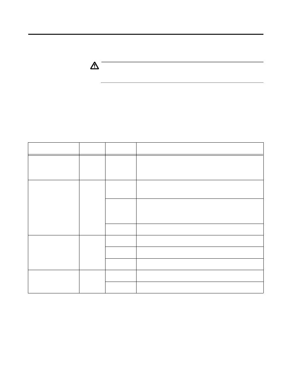
Table 2-1 Switch LEDs
LED
Color
State
Description
Power (system)
Green
On
The switch is receiving power, voltage is within
the acceptable range, and the power supply is
working.
Fault (system)
Red
On
The switch or management software is
malfunctioning.
Flashing
The switch is booting, running diagnostics, writing
images to FLASH, or transferring files via
XMODEM.
Off
Normal operation.
Link/Receive
(port, top row)
Green
On
There is a physical link with a device.
Flashing
The port is receiving packets.
Off
No link.
100 M
(port, bottom row)
Amber
On
The port is operating at 100 Mbps.
Off
The port is operating at 10 Mbps.