Allied Telesis AT-8126XL User Manual
Page 20
Hardware Description
1-10
Like the switch’s station ports, the uplink ports are associated with
two LEDs that indicate port speed and valid physical link. See Figure
1-5 for the location of the Uplink Ports’ LEDs. The LEDs are further
described in Chapter2, T able 2-1 on page 2-4.
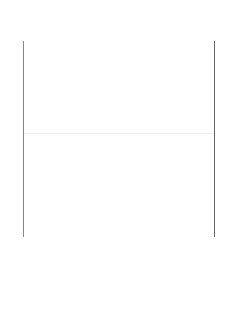
Table 1-2 Media Dependent Adapter Features
Adapter
Connector
Type
Description
AT-A10
RJ45
"
Auto-negotiationg 10Base-T/100Base-TX Fast Ethernet port
"
Auto-negotiating 10/100 Mbps and duplex mode
"
Maximum segment length: 330 ft (100 m), Category 5 UTP cable
AT-A11
Fiber SC
"
100Base-FX Fast Ethernet port
"
Default transmission speed fixed at 100 Mbps
"
Multimode SC fiber connector
"
Auto-negotiating duplex mode (100 Mbps only)
"
Maximum segment length: 1.25 mi (2 km), 50/125- and 62/5/125-
micron multimode fiber cable for full-duplex; 1,351 ft (412 m) for
half-duplex
AT-A20
Fiber MT-RJ
"
100Base-FX Fast Ethernet port
"
Default transmission speed fixed at 100 Mbps
"
Multimode MT-RJ fiber connector
"
Auto-negotiating duplex mode (100 Mbps only)
"
Maximum segment length: 1.25 mi (2 km), 50/125- and 62/5/125-
micron multimode fiber cable for full-duplex; 1,351 ft (412 m) for
half-duplex
AT-A21
Fiber VF-45
"
100Base-FX Fast Ethernet port
"
Default transmission speed fixed at 100 Mbps
"
Multimode VF-45 fiber connector
"
Auto-negotiating duplex mode (100 Mbps only)
"
Maximum segment length: 1.25 mi (2 km), 50/125- and 62/5/125-
micron multimode fiber cable for full-duplex; 1,351 ft (412 m) for
half-duplex