Port leds, Rs232 connector, Reset button – Allied Telesis AT-8126XL User Manual
Page 17: Port leds -7 rs232 connector -7 reset button -7
AT-8118, AT-8124XL, and AT-8126XL Installation Guide
1-7
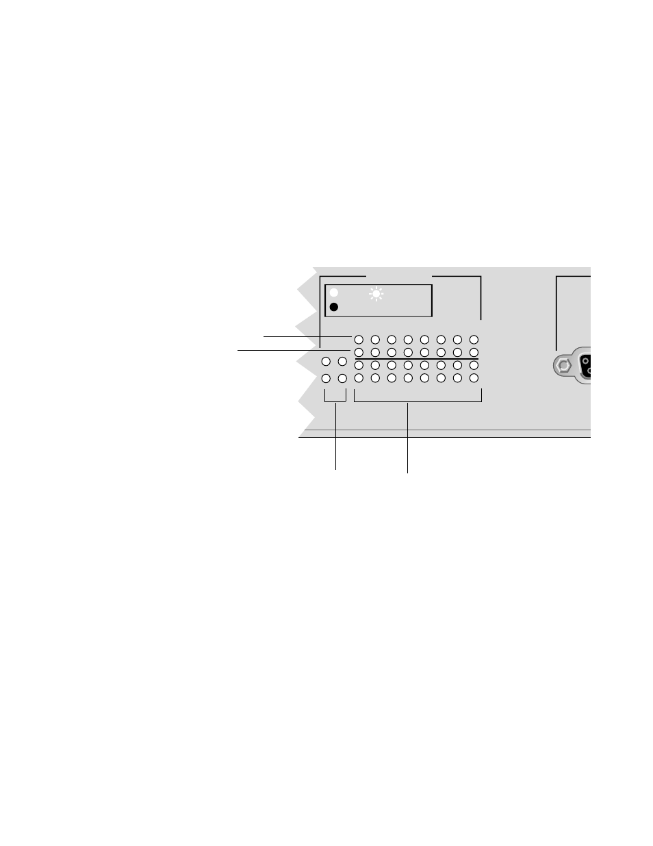
Port LEDs
Each switch port and uplink port is associated with two LEDs
indicating the following:
" Valid physical link with a device and packets being received, as
indicated by the top row of LEDs
" Speed of transmission, 10 Mbps or 100 Mbps, as indicated by
the bottom row of LEDs
Figure 1-5 is a closeup of the AT-8118’s port LEDs. (The
AT-8126XL is similar to the AT-8118. The AT-8124XL does not
have Uplink Port LEDs.)
Figure 1-5 Port LEDs
The LEDs are further described in Chapter2, T able 2-1 on page 2-4.
RS232 Connector
The RS232, DB-9 female connector provides out-of-band local
management via a VT100 terminal or MS-Windows’ VTERM terminal
emulation using a straight-through cable.
Reset Button
The Reset button is used to reset the switch with power still applied.
It is mainly used for diagnostics or resetting switch statistics as
recorded by the management software, Omega. You can also reset
the switch via the software. Download the AT-S21 Software
Management User’s Guide from the web a
www.alliedtelesyn.com for more information.
TERM
PORT ACTIVITY
1
3
5
7
9
11
13
15
2
B
A
4
6
8
10
12
14
16
15X
16X
LINK /
RECEIVE
100M
Link and Received Packets LED (Green)
Transmission Speed LED (Amber)
Uplink Port LEDs
Station Port LEDs