Table 9: at-mr912tx models, At-mr912tx-10a, Standalone – Allied Telesis AT-MR912TX User Manual
Page 53: At-mr912tx-19a, Stackable, At-mr912tx-20a, At-mr912tx-29a, At-mr912tx-30a, At-mr912tx-39a, Figure18: rj-45 connector
AT-MR912TX Installation Manual
33
Product Models
Six different models of the AT-MR912TX hub are available, depending on
voltage, power cords and configuration options. Table 9 details the six model
types.
Table 9: AT-MR912TX Models
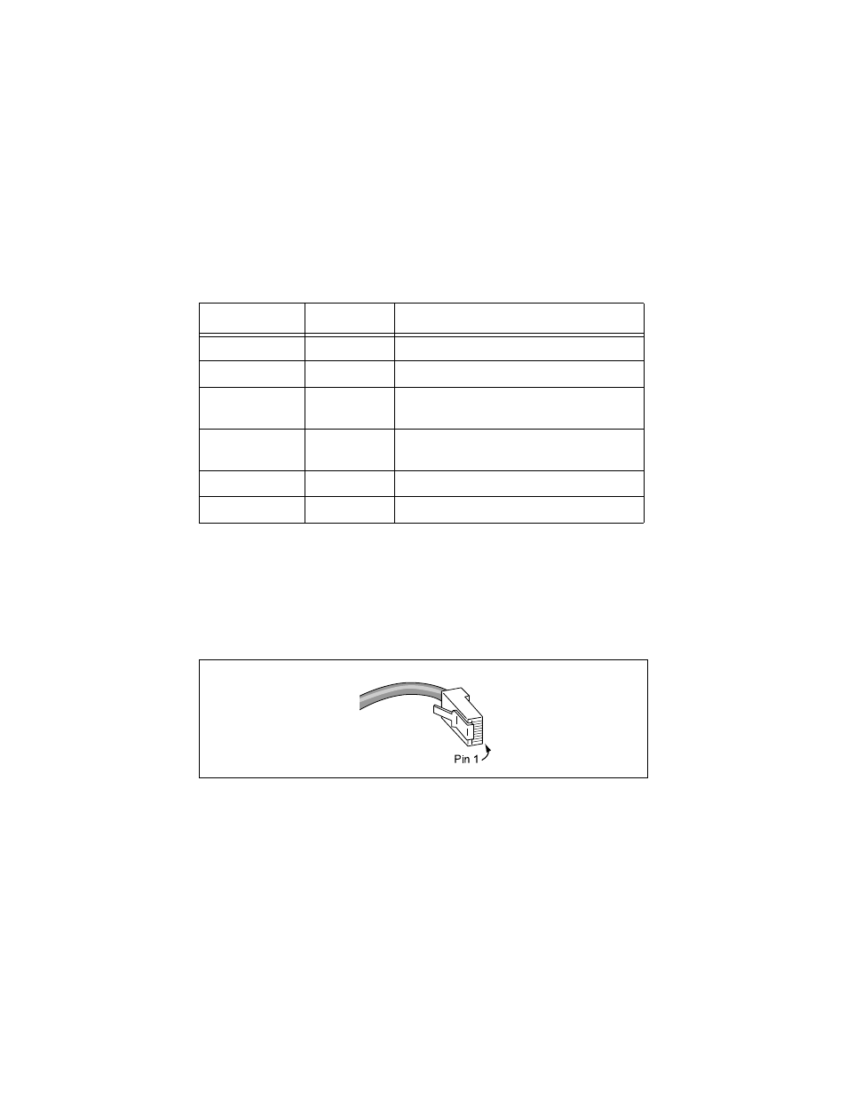
UTP (RJ-45) Connector
A generic RJ-45 connector is shown in Figure 18. For a 100Base-TX link
between a hub, a repeater or a Medium Attachment Unit (MAU) you will need
a crossover cable or the use of port 12 of your AT-MR912TX. For a connection
to a Network Interface Controller (NIC), the cable is wired straight through.
Figure 18: RJ-45 Connector
Model Number
Configuration
Voltage/Power Cord Requirement
AT-MR912TX-10A
Standalone
100-120 VAC; power cord for U.S.
AT-MR912TX-19A
Stackable
100-120 VAC; power cord for U.S.
AT-MR912TX-20A
Standalone
200-240 VAC; power cord for Continental
Europe
AT-MR912TX-29A
Stackable
200-240 VAC; power cord for Continental
Europe
AT-MR912TX-30A
Standalone
200-240 VAC; power cord for United Kingdom
AT-MR912TX-39A
Stackable
200-240 VAC; power cord for United Kingdom