Table 4: front panel leds, Power (pwr), Green – Allied Telesis AT-MR912TX User Manual
Page 26: Lighted: power on, Unlighted: power off, Collision (col), Amber, Lighted: data collision occurring, Link/activity, Lighted: adapter connected to hub
Product Description
6
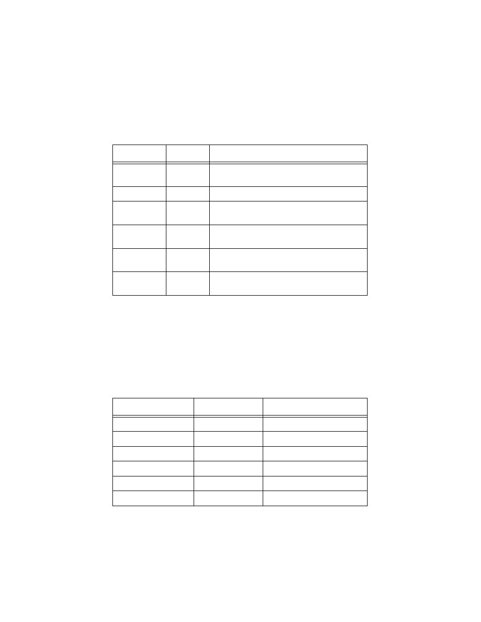
Table 4 on page 6 details the purpose, color and functional description of each
LED.
Table 4: Front Panel LEDs
AT-MR901 Stacking Module
Models AT-MR912TX-10A, AT-MR912TX-20A or AT-MR912TX-30A have a
blank faceplate. The AT-MR901 Stacking Module is an optional feature on
these models.
Models AT-MR912TX-19A, AT-MR912TX-29A or AT-MR912TX-39A include
ATI’s AT-MR901 Stacking Module as a standard feature.
Table 5: AT-MR901TX Stacking Module
LED
Color
Description
Power (PWR)
Green
Lighted: Power on
Unlighted: Power off
Collision (COL)
Amber
Lighted: Data collision occurring
Link/Activity
Green
Lighted: Adapter connected to hub
Flickering: Data receiving
100Base-FX
Module
Green
Lighted: Power on
Unlighted: Power off
Error
Yellow
Flashing: Data error occurring
Lighted: Partition and isolation of port
Utilization
Green
Hub traffic of the Fast Ethernet bandwidth
(1%, 8%, 16%, 32%, 64%)
Model Number
Configuration
AT-MR901 included?
AT-MR912TX-10A
Standalone No
AT-MR912TX-19A
Stackable
Yes
AT-MR912TX-20A
Standalone
No
AT-MR912TX-29A
Stackable
Yes
AT-MR912TX-30A
Standalone
No
AT-MR912TX-39A
Stackable
Yes