Figure14: cascaded hubs, Make sure the package includes all of the requi, Make sure you have the correct cables for the c – Allied Telesis AT-MR912TX User Manual
Page 39: Remove each hub to be included in the cascaded, Arrange both at-mr912tx hubs such that the back, Insert the female end of the power cord into th, Insert the male end of the power cord into the, Cascaded installation
AT-MR912TX Installation Manual
19
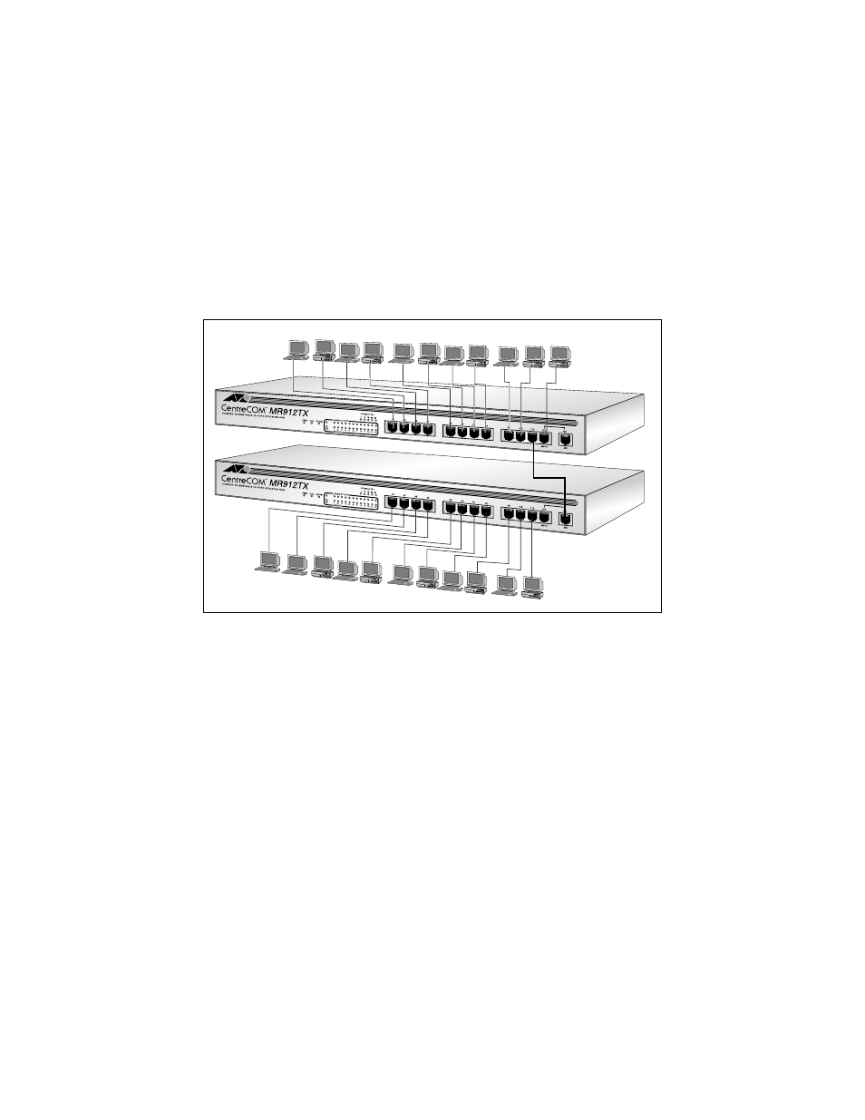
Cascaded Installation
You do not need to upgrade a standalone AT-MR912TX hub to enable
cascading. From the illustration below, connection is established between the
MDI Port 12 on one hub (the bottom hub in this example) and any port (1
through 12) on a second AT-MR912TX hub (Port 11 on the upper hub in the
example).
Figure 14: Cascaded Hubs
1. Make sure the package includes all of the required parts
2. Make sure you have the correct cables for the connection between cascaded
hubs as well as between the network ports on each hub and the attached
devices.
3. Remove each hub to be included in the cascaded hub configuration from its
shipping package and store the box and packing materials in a safe place
in case the unit needs to be transferred in the future.
4. Arrange both AT-MR912TX hubs such that the back panel on each hub is
within 5 meters (16.4 feet) of the other.
5. Insert the female end of the power cord into the Power Receptacle on the
back of the unit.
6. Insert the male end of the power cord into the into an electrical output of
the appropriate power.