Install the brackets as indicated in the follow, Figure16: installing stacking brackets, Attach the power cords of all units – Allied Telesis AT-MR912TX User Manual
Page 43: Use the scsi type ii cable to connect the out p, Do not match out to out or in to in when connec, Repeat the preceding steps until you have conne, Check the front of each hub in the stack to mak, Plug all category 5 stp/utp cables in the 100ba
AT-MR912TX Installation Manual
23
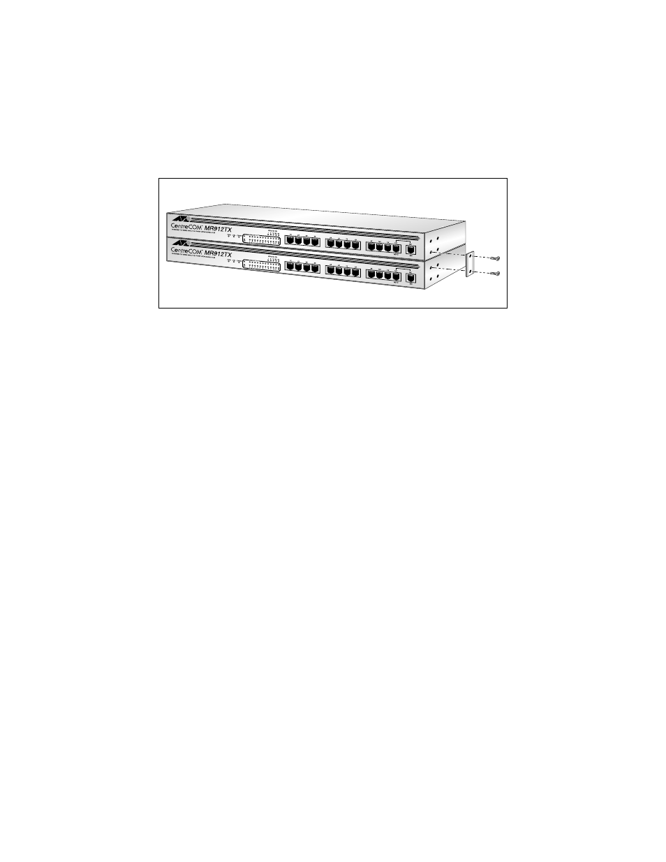
2. Install the brackets as indicated in the following figure.
Figure 16: Installing Stacking Brackets
3. Attach the power cords of all units.
4. Use the SCSI Type II cable to connect the OUT port on the bottom unit
with the IN port on the upper unit. Continue this process until you have
connected the final hub.
5. Do not match OUT to OUT or IN to IN when connecting the stackable
ports of any pair of hubs.
6. Repeat the preceding Steps until you have connected up to a maximum of
six AT-MR912TX hubs in a single stack
7. Check the front of each hub in the stack to make sure all green power
(PWR) LEDs are illuminated.
8. Plug all Category 5 STP/UTP cables in the 100Base-TX network ports
(RJ-45 connectors) on the front panel of each unit.