Table 1: at-mr901 stacking module option, At-mr901, Table 2: at-mr902 fiber optic connector options – Allied Telesis AT-MR912TX User Manual
Page 23: At-mr902-02, At-mr902-03
AT-MR912TX Hub Installation Manual
3
Stacked Hub Configuration
Your AT-MR912TX hub has a bay which accepts ATI’s AT-MR901 Stacking
Module. The AT-MR901 Stacking Module is a standard feature with three
models of the AT-MR912TX: the AT-MR912TX-19A, AT-MR912TX-29A and
the AT-MR912TX-39A.
Additionally, the above models also include two metal brackets, with four
panhead screws and lock washers, which can be used to attach units together.
This procedure is discussed in Chapter 2.
The AT-MR901 Stacking Module is an optional feature (it can be purchased
separately) with the following models: the AT-MR912TX-10A,
AT-MR912TX-20A and the AT-MR912TX-30A.
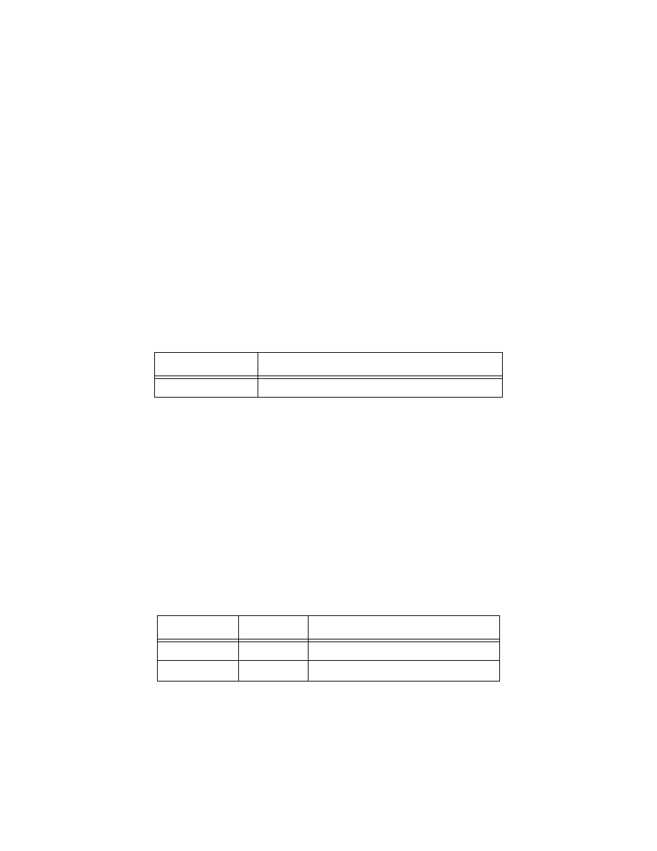
The part number is shown in the following table.
Table 1: AT-MR901 Stacking Module Option
When the AT-MR901 Stacking Module is installed, a fully populated stack will
support six hubs. That is, a stack of six units can be physically connected while
logically still appearing to be a single hub — but with additional ports. In a
fully populated stacked hub configuration, your 100 Mbps network will
support as many as 72 network nodes or devices (6 hubs x 12 ports = 72
nodes).
Fiber Optic Cable Configurations
The AT-MR912TX hub also has a bay which accepts ATI’s optional AT-MR902
100Base-FX Module for connectivity to either a fiber backbone or any other
device with fiber optic capabilities. This feature will also be discussed later.
Two different types of fiber optic connectors are available: Straight Tip (ST) or
Subscriber Channel (SC).
Table 2: AT-MR902 Fiber Optic Connector Options
Model Number
Part Number
AT-MR901
990-09139-00
Model Number
Configuration
Part Number
AT-MR902-02
SC
990-09140-02
AT-MR902-03
ST
990-09140-03