Slide the at-mr901 stacking module into the bac, Figure15: installing an at-mr901 stacking module, Secure the stacking module in place with the fo – Allied Telesis AT-MR912TX User Manual
Page 42: In a chassis, place up to six at-mr912tx hubs s, Chassis or stacking brackets
Installation
22
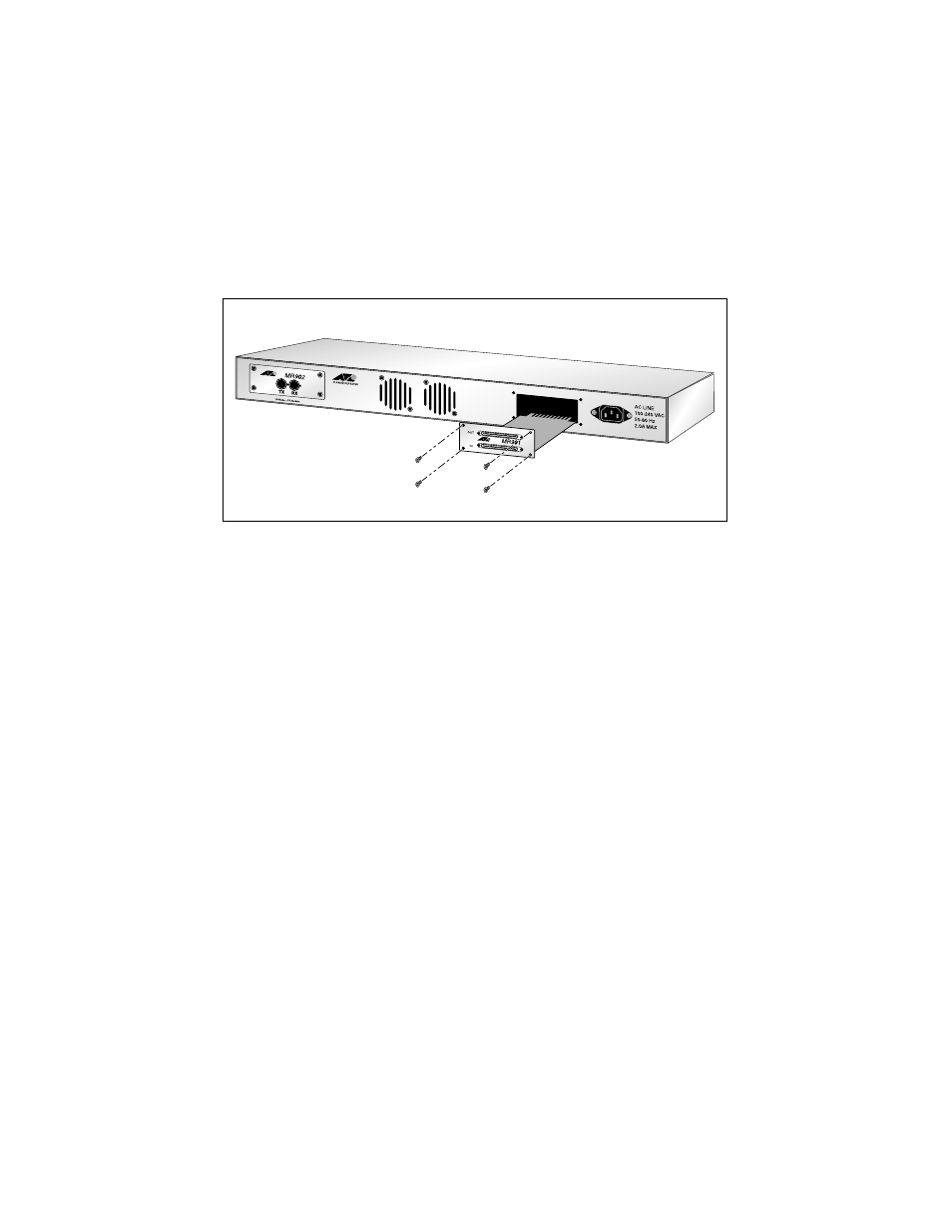
3. Slide the AT-MR901 Stacking Module into the back panel port opening, as
shown in Figure 15. Ensure that the module is seated in the internal
connector and the module faceplate is flush with the surface of the back
panel.
Figure 15: Installing an AT-MR901 Stacking Module
4. Secure the stacking module in place with the four screws you removed in
Step 2 above.
Chassis or Stacking Brackets
You are now ready to connect the AT-MR912TX hub with another
AT-MR912TX hub using the SCSI Type II Stacking cable.
Use the following procedures to connect multiple AT-MR912TX units in a
stacked hub configuration:
1. In a chassis, place up to six AT-MR912TX hubs such that the uplink ports
on the back panel of the units align.
Alternately, you can connect two AT-MR912TX hubs with the stacking
brackets that are included with the AT-MR912TX-19A, AT-MR912TX-29A
and the AT-MR912TX-39A models as well as with the AT-MR901 Stacking
Module upgrade package.