Connectors, Figure20: connector pin numbers, Table 3: pin assignments – Allied Telesis AT-MR820TR User Manual
Page 55
AT-MR420TR and AT-MR820TR Installation Guide
33
Connectors
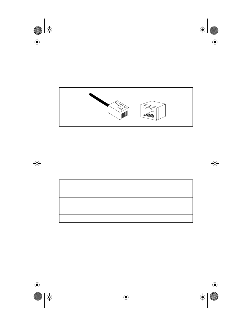
Notice how the pins are numbered in Figure 20. Be sure to hold the
connectors in the same orientation when connecting the wires to the
pins.
Figure 20:
Connector Pin Numbers
Each twisted-pair link segment must have a male connector attached
to both ends. According to the 10Base-T specification, pins 1 and 2 on
the connector are used for transmitting data; pins 3 and 6 are used for
receiving data, as shown in Table 3. The TX and the RX in Table 3
represent Transmitted Data and Ready Data, respectively.
Table 3: Pin Assignments
*The “+” and “-” signs are used to represent the polarity of the two wires that make up each
wire pair.
Pin
Assignment *
1
TX+
2
TX-
3
RX+
6
RX-
1
8
8
1
MRx20TR(STP/UTP)_BookA Page 33 Thursday, April 3, 1997 5:24 PM