10base5 backbone, Figure17: 10base5 backbone topology – Allied Telesis AT-MR820TR User Manual
Page 50
Topology
28
❑
In the MDI configuration — the slide switch is to the left — you
can connect the 10Base-T port to another 10Base-T internal
crossover port, that is, a repeater using straight-through
twisted pair cable to form an interrepeater link. See Figure 16.
If you use this port to connect repeaters to each other, the RJ45 pinout
switch must be set to MDI. The MDI position is a repeater pinout which
automatically swaps the TX and RX pinouts so that they do not conflict
with the TX and RX ports at the other end of a straight-through cable.
If you connect a straight-through cable to another repeater or DTE and
the Link LEDs on the respective units are not on, change the position
of the MDI/MDI-X switch to obtain continuity as indicated by active
Link lights. The repeater will not be damaged if the MDI/MDI-X switch
is in the wrong position.
In general, if you install an RJ45 port cable, and the Link LED does not
light, then simply change the position of the MDI/MDI-X slide switch
and see if the Link LED lights.
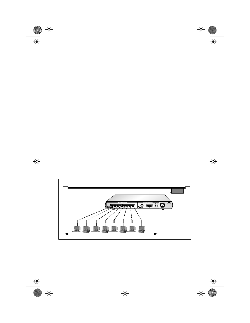
10Base5 Backbone
Figure 17 illustrates a single multiport 10Base-T AT-MR820TR Micro
Repeater connecting to a thick Ethernet backbone using a transceiver.
Figure 17: 10Base5 Backbone Topology
100 Meters
maximum
Category 3-5
STP/UTP cable
wired Pin to Pin
AUI cable
Coaxial Backbone
Ethernet
Transceiver
MRx20TR(STP/UTP)_BookA Page 28 Thursday, April 3, 1997 5:24 PM