Figure15: at-mr820tr backbone topology, Mdi/mdi-x switch and uplink port, Backbone networks – Allied Telesis AT-MR820TR User Manual
Page 48
Topology
26
Backbone Networks
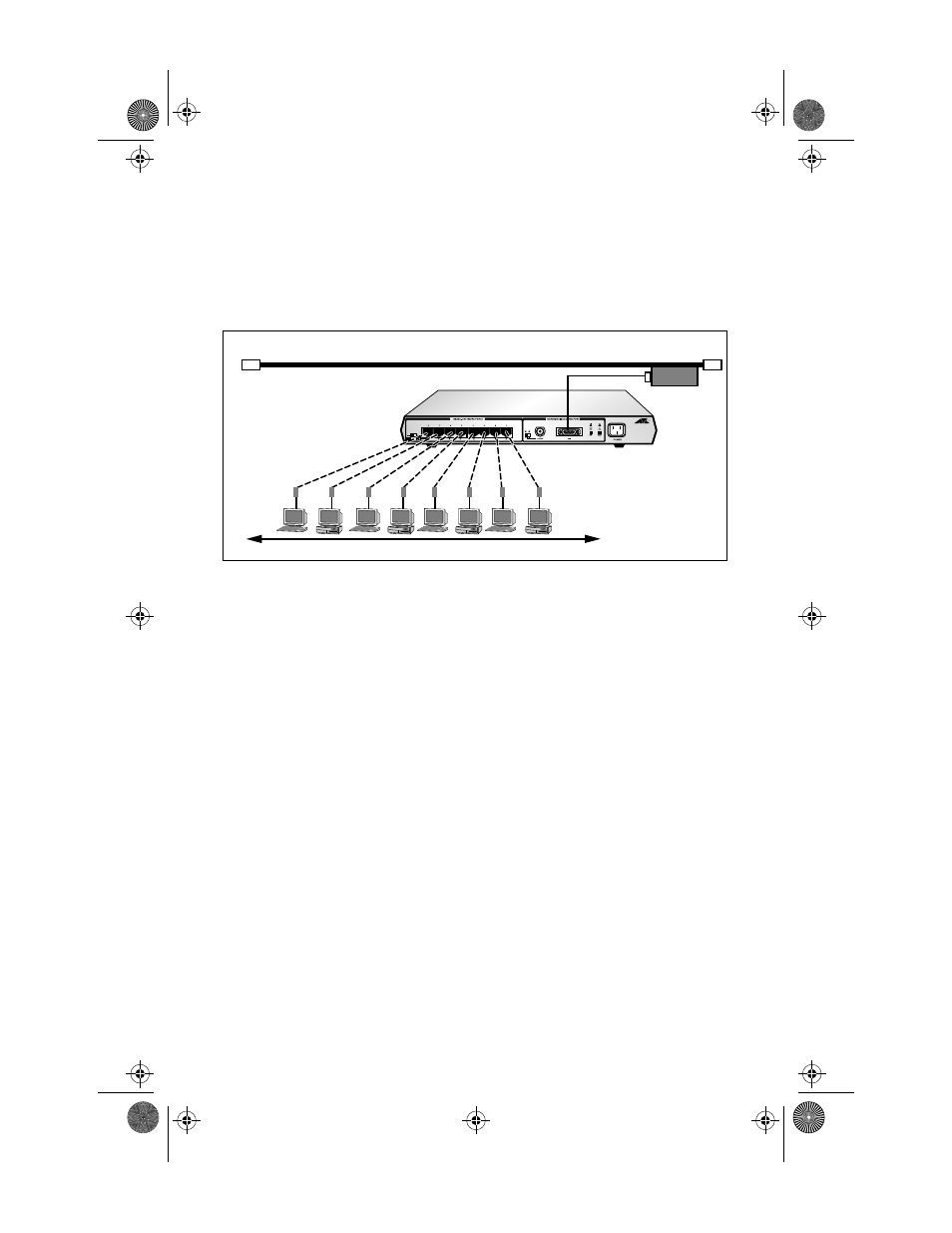
The most straightforward topology is a backbone network. Figure 15
show a backbone network topology with the AUI port attaching to a
coaxial Ethernet cable.
Figure 15: AT-MR820TR Backbone Topology
In a backbone network topology, each workgroup has its own local
network and the backbone is used to link the various workgroups
through the bridges. The advantages of a backbone network topology
are twofold:
❑
When the backbone network is operating correctly, any
problem within a sub-network does not affect other sub-
networks.
❑
Since faults are isolated to a single sub-network, they are
easier to locate.
MDI/MDI-X Switch and Uplink Port
While any RJ45 port can be used to cascade repeaters, port 4/8 has
been specifically designed with an uplink (cascading) capability, by
providing a Media Dependent Interface (MDI/MDI-X) switch.
Cascading through port 4/8 means if a single, standalone
AT-MR420TR/AT-MR820TR Micro Repeater can support 4/8 ports,
when a second AT-MR420TR/AT-MR820TR Micro Repeater is
uplinked (cascaded) using the port 4/8 of the first unit to any port of a
100 Meters
maximum
Category 3-5
STP/UTP cable
wired Pin to Pin
AUI cable
Coaxial Backbone
Ethernet
Transceiver
MRx20TR(STP/UTP)_BookA Page 26 Thursday, April 3, 1997 5:24 PM