Topology, Figure12: at-mr420tr standalone topology, Chapter 4 – Allied Telesis AT-MR820TR User Manual
Page 45
23
Chapter 4
Topology
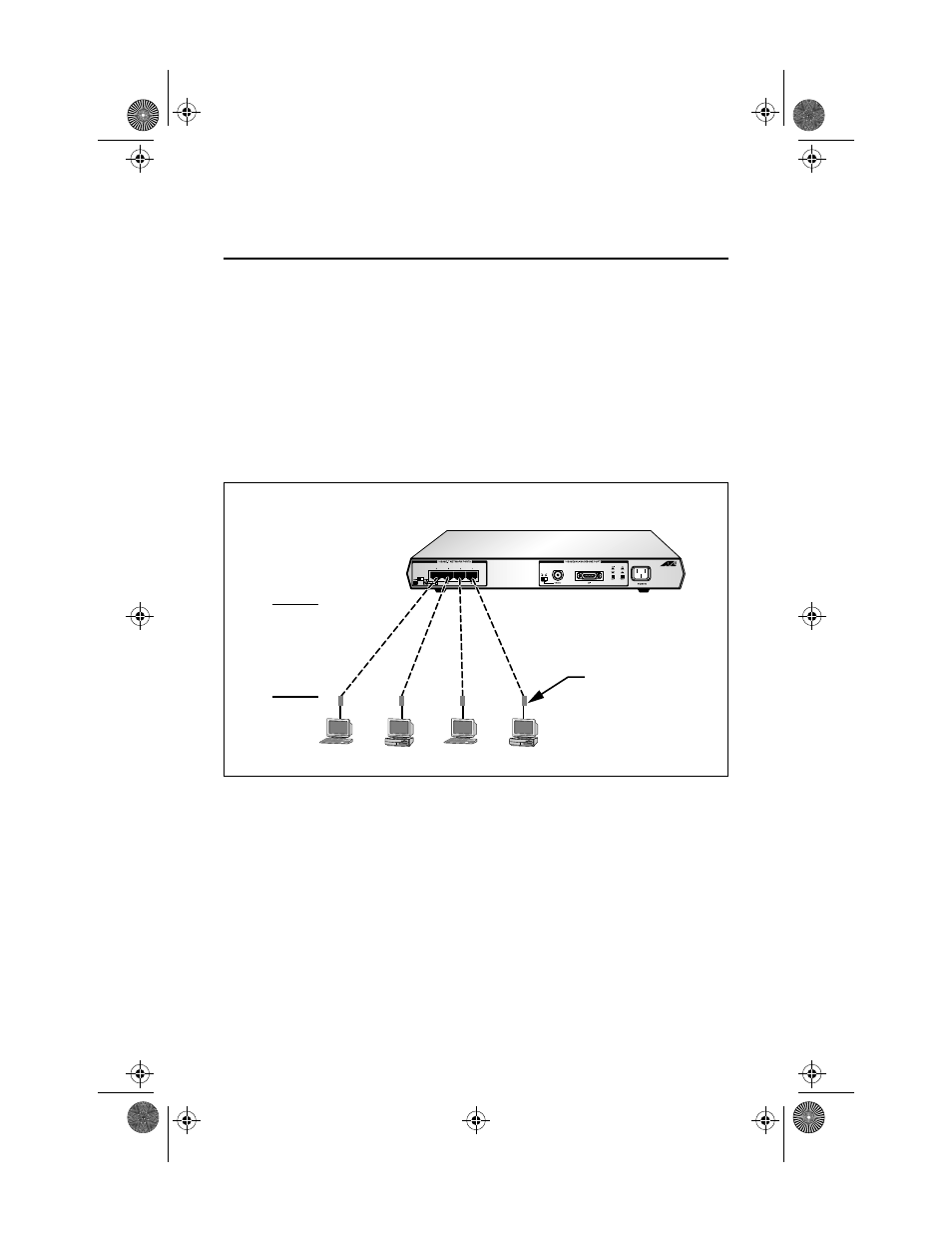
Standalone Topology
Figure 12 shows a standalone topology. Four workstations are
connected directly to the repeater through the repeater’s RJ45 ports.
Figure 12: AT-MR420TR Standalone Topology
Cascade Topology
A shared Ethernet network can be expanded by interconnecting
repeaters (cascading) through the UTP ports. Figure 13 shows a
cascaded topology using four repeaters which is the maximum number
of micro repeaters and nodes in a single segment: four micro repeaters
with ten (AT-MR420TR)/twenty-six (AT-MR820TR) ports. Its design
complies with the four-repeater rule. Additional UTP ports are
available if the AUI port is used for cascading.
100 Meters
TP cable
wired
Pin to Pin
10BaseT
Tranciever
MRx20TR(STP/UTP)_BookA Page 23 Thursday, April 3, 1997 5:24 PM