Figure16: uplink port for mr420tr/820tr – Allied Telesis AT-MR820TR User Manual
Page 49
AT-MR420TR and AT-MR820TR Installation Guide
27
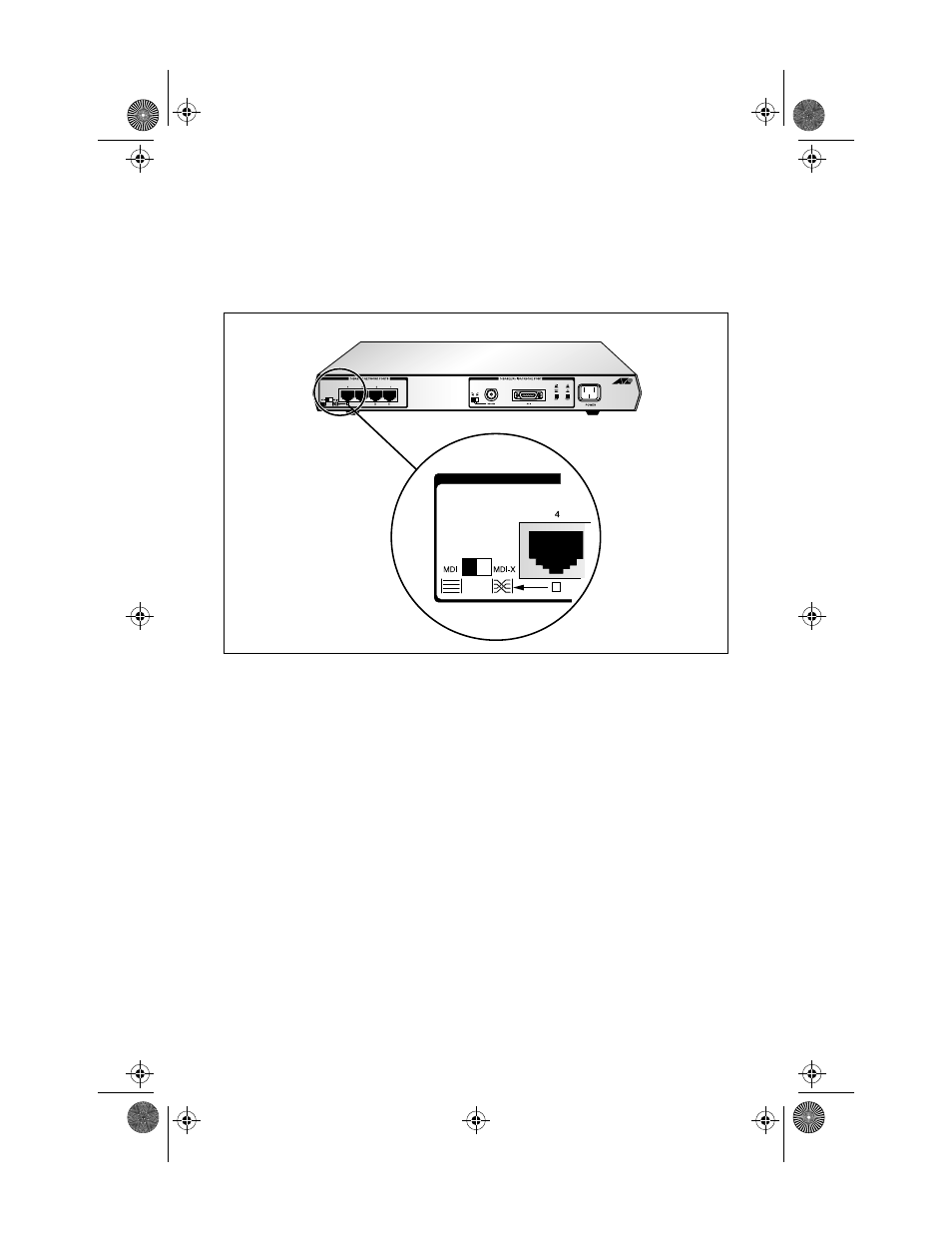
second unit. A maximum of four repeaters (the four repeater rule) can
be interconnected. The network effectively consists of 6 nodes for the
AT-MR420TR and 14 nodes for the AT-MR820TR. The Uplink port is
located on the back panel, as shown in Figure 16.
Figure 16: Uplink Port for MR420TR/820TR
Port 4/8 has the ability to become a dedicated uplink port. To facilitate
this process, it uses a Media Dependent Interface (MDI/MDI-X) switch.
An MDI/MDI-X switch is a crossover/straight-through cable selection
slide switch. As shown in Figure 16, the MDI/MDI-X switch converts
the 10Base-T (RJ45) Port 4/ 8, to an uplinkable port that allows one
repeater to connect to another repeater without requiring special
crossover cables.
The default setting for the RJ45 pinout switch is MDI-X (standard
RJ45 port), which means the slide switch is to the right.
❑
In the default MDI-X configuration you can connect the
10Base-T port to a workstation or to any other DTE (that is,
node).
MRx20TR(STP/UTP)_BookA Page 27 Thursday, April 3, 1997 5:24 PM