Figure14: terminator switch – Allied Telesis AT-MR820TR User Manual
Page 47
AT-MR420TR and AT-MR820TR Installation Guide
25
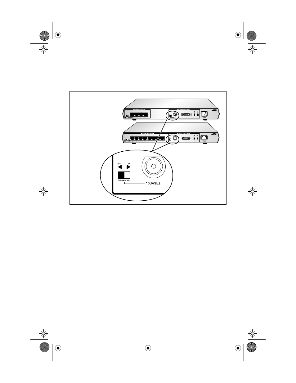
the termination switch. Figure 14 shows the location of the two-
position 50
Ω
Terminator switch. The switch is either ON (the default)
or OFF.
Figure 14: Terminator Switch
OFF (disabled) — When installing a hub at an intermediate point of a
thinnet cable, a BNC-T connector must be used to connect the cable to
the backbone port and the terminator switch must be disabled. See
Figure 14.
ON (enabled) — When installing a hub at the end of the cable, if you
need to remove the BNC-T connector and the terminator, the backbone
port must be connected directly to the thinnet cable. The terminator
switch must be enabled. This provides the 50 ohm termination that is
required.
❑
Use the OFF position to disable termination if you are
installing a link segment with a BNC-T connector on this port.
❑
Use the ON position to enable termination if you are installing
a link segment without a BNC-T connector at this port, and if
the unit is at the end of the cable.
MRx20TR(STP/UTP)_BookA Page 25 Thursday, April 3, 1997 5:24 PM